Tensioner unit, oscillating lever, and tensioner
A technology of tensioning device and swing lever, which is applied in the direction of transmission device, machine/engine, belt/chain/gear, etc., can solve the problem that the tensioning device 810 does not operate, so as to suppress malfunction, suppress manufacturing cost, and reduce noise effect
- Summary
- Abstract
- Description
- Claims
- Application Information
AI Technical Summary
Problems solved by technology
Method used
Image

Examples
Embodiment 1
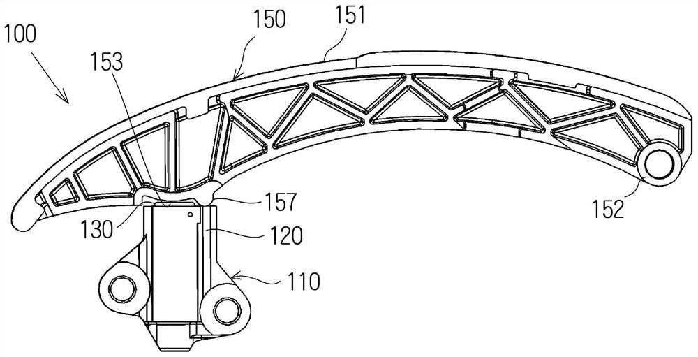
[0064] The tensioner unit 100 according to the first embodiment of the present invention will be described with reference to the drawings.
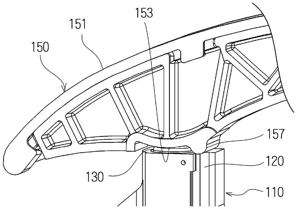
[0065] The tensioner unit 100 is composed of a tensioner 110 and a swing lever 150 .
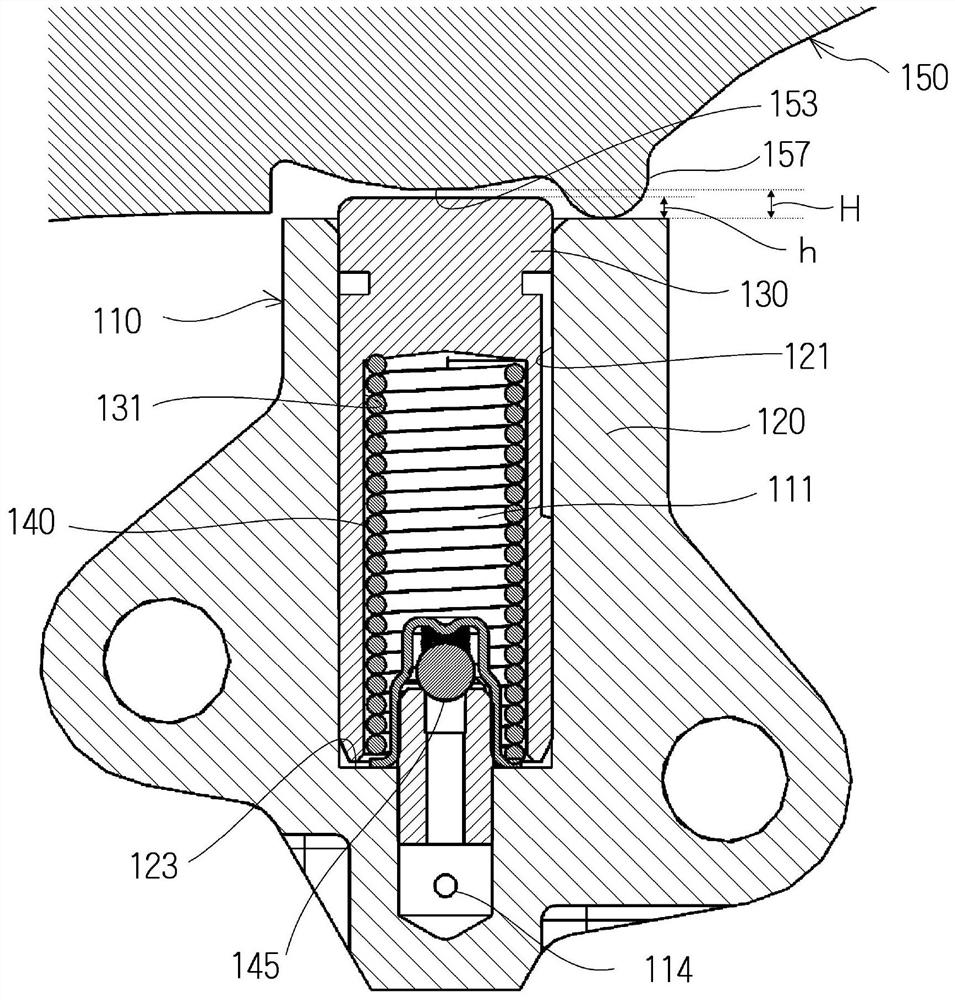
[0066] Such as Figure 1 to Figure 3 As shown, the tensioning device 110 includes: a tensioning device main body 120 having a cylindrical plunger receiving hole 121 with one side open; a cylindrical plunger 130 slidably inserted into the plunger receiving hole 121; And the urging mechanism is retractably accommodated in the pressure oil chamber 111 formed between the plunger receiving hole 121 and the rear end side of the plunger 130, and urges the plunger 130 in the protruding direction.
[0067] The urging mechanism is constituted by a coil spring 140 housed in the cylindrical recess 131 of the cylindrical plunger 130 and compressed between the bottom 123 of the plunger receiving hole 121 .
[0068] The tensioner 110 of the present embodiment fills ...
Embodiment 2
[0078] Compared with the tensioner unit 100 according to the above-mentioned first embodiment, the tensioner unit according to the second embodiment of the present invention has a groove, a through hole or a bottomed hole on the front end surface of the protrusion.
[0079] For example, if Figure 4 As shown, the swing rod 250A has an overall semi-cylindrical protrusion 257A extending across the entire width of the swing rod 250A. Two groove-like grooves 261, 261 extending in the moving direction of the chain (the parts having the same structure as those of the tensioner unit 100 according to the first embodiment are denoted by the same reference numerals, and are also shown in the following drawings. same).
[0080] Also, for example Figure 5 As shown, the swing rod 250B has an overall semi-cylindrical protrusion 257B extending across the entire width of the swing rod 250B. One groove-shaped groove 262 extending in the width direction of the swing lever 250B.
[0081] Al...
Embodiment 3
[0084] The tensioner unit 300 according to the third embodiment of the present invention differs from the tensioner unit 100 according to the above-mentioned first embodiment in the position where the protrusion is formed.
[0085] Such as Figure 8 As shown, the protruding portion 357 of the swing lever 350 according to the present embodiment is arranged as follows. side, contact the top end surface of the tensioner main body 120 of the tensioner 110 .
[0086] Even if a sufficient space cannot be secured at the position where the protrusion 157 is formed in the tensioner unit 100 according to the first embodiment, it can be appropriately selected as in the tensioner unit 300 according to the third embodiment. The position of the protruding portion 357 has a high degree of design freedom.
PUM
 Abstract
Description
Claims
Application Information
 - Generate Ideas
- Intellectual Property
- Life Sciences
- Materials
- Tech Scout
- Unparalleled Data Quality
- Higher Quality Content
- 60% Fewer Hallucinations
Browse by: Latest US Patents, China's latest patents, Technical Efficacy Thesaurus, Application Domain, Technology Topic, Popular Technical Reports.
© 2025 PatSnap. All rights reserved.Legal|Privacy policy|Modern Slavery Act Transparency Statement|Sitemap|About US| Contact US: help@patsnap.com