
Fast automatic rolling, slitting and counting top machine equipment

A counting type, top machine technology, applied in the field of top machine, can solve the problems of poor quality, sparse wool, sparse top short hair, etc., to achieve uniform distribution, good quality, and improve the winding speed.

Inactive Publication Date: 2020-09-22
UNIV OF SHANGHAI FOR SCI & TECH
View PDF19 Cites 0 Cited by
  • Summary
  • Abstract
  • Description
  • Claims
  • Application Information

AI Technical Summary

Problems solved by technology

However, the structure of the rotating frame-type wool guiding device determines that its rotational speed cannot be improved after it reaches a higher speed. It is relatively sparse, which makes the short hair on the produced top very sparse, which cannot meet the requirements of the top.
[0007] Secondly, if the method of improving the supply quantity of wool is adopted to solve the problem of sparse short hairs on the above-mentioned wool tops, a new problem will be caused, that is, a plurality of wool yarns will be entangled with each other under the guidance of the rotating frame-type wool guide equipment , and the multiple yarns that are entangled will be cut to form short hair after being wound on the iron wire. It is inclined instead of flat, which results in rough appearance and poor quality of tops formed by short hairs
In particular, it cannot meet the quality requirements of wool tops (about 30cm to 50cm in length) for handmade DIY.

Method used


Image

  • Fast automatic rolling, slitting and counting top machine equipment
  • Fast automatic rolling, slitting and counting top machine equipment
  • Fast automatic rolling, slitting and counting top machine equipment

Examples


Embodiment Construction

[0030] In order to make the technical means, creative features, goals and effects of the present invention easy to understand, the following embodiments will specifically illustrate the present invention's fast automatic winding, slitting, counting and counting wool top machine equipment in conjunction with the accompanying drawings.

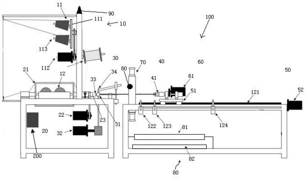
[0031] figure 1 It is a schematic structural diagram of the fast automatic winding, slitting and counting top machine equipment in the embodiment of the present invention.

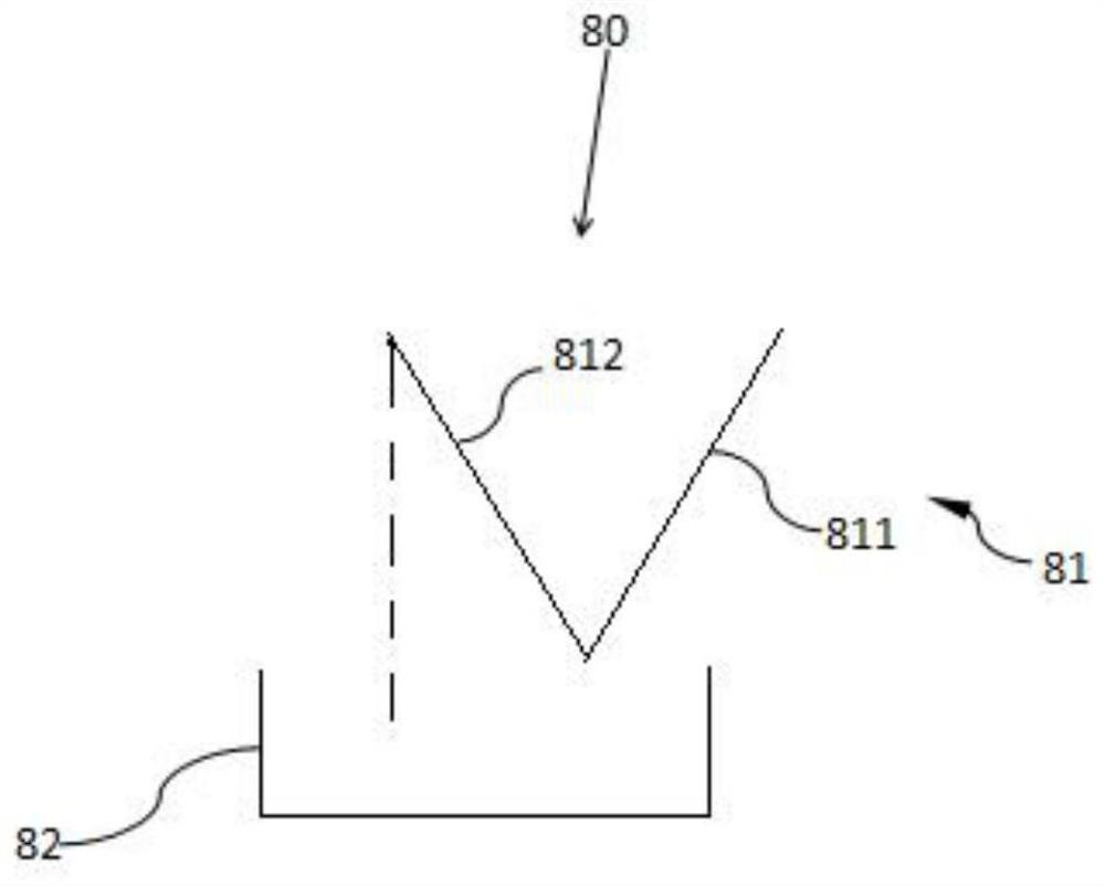
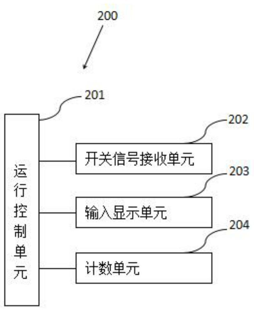
[0032] like figure 1 As shown, the fast automatic rolling, cutting and counting type wool top machine equipment 100 in this embodiment is used for rapid production of wool tops, including a frame, a wire supply mechanism 10, a winding mechanism 20, a wire feeding mechanism 30, a clamping mechanism 40, Wire drawing mechanism 50 , winding mechanism 60 , cutting mechanism 70 , top storage mechanism 80 , alarm mechanism 90 and control unit 200 . Wherein, the output part includ...


PUM


Abstract

The invention provides fast automatic rolling, slitting and counting top machine equipment, which is used for quickly producing tops and counting the tops. The top machine equipment is characterized by comprising a yarn supply mechanism with a yarn supply unit, a winding frame with a rotating frame, a cutting mechanism, and a control part with an operation control unit and a counting unit, whereinthe yarn supply unit comprises a rotating table and a plurality of yarn wheels fixed on the rotating table; a yarn is wound around each yarn wheel; the operation control unit controls the rotating table and the rotating frame to rotate synchronously; before the yarns are cut, the counting unit is controlled to increase the number of the tops by 1, and the cutting mechanism is controlled to cut off the tops; the rotating direction of the rotating table is viewed from one side that the yarns leave the rotating table; the rotating direction of the rotating frame is viewed from one side that theyarns leave the rotating frame; and the rotating direction and the rotation speed of the rotating table are the same as those of the rotating frame.

Description

technical field [0001] The invention relates to the field of top knitting machines, in particular to a fast automatic rolling, slitting and counting top knitting machine equipment. Background technique [0002] The structure of the traditional wool top machine is relatively complicated and occupies a large area. It can only produce long wool tops, and the produced long wool tops are coiled into a large roll on the take-up device. But, because the length of the commonly used wool top is 30cm~5m, therefore, after existing wool top machine produces long wool top, also must carry out secondary processing to long wool top so that long wool top is cut to obtain the wool top of suitable length. This secondary processing is usually done manually, so the efficiency is low and the cost is high. [0003] In addition, during the secondary processing of long wool slivers, manual counting is generally used to count the processed wool slivers. The counting results are not accurate, and th...

Claims


Application Information

Patent Timeline
IPC IPC(8): B65H51/18B26D1/08B26D5/12B26D7/06B26D7/28B26D7/32
CPCB26D1/08B26D5/12B26D7/06B26D7/28B26D7/32B65H51/18
Inventor 金爱娟李少龙
Owner UNIV OF SHANGHAI FOR SCI & TECH
Learn More