Humidity micro power generation device based on dust-free paper and ink and preparation method and application thereof
A technology of power generation device and dust-free paper, which is applied in the directions of generators/motors, electrical components, etc., can solve the problems of short stabilization time, complicated steps, and high preparation costs, and achieve the effect of cost saving
- Summary
- Abstract
- Description
- Claims
- Application Information
AI Technical Summary
Problems solved by technology
Method used
Image
Examples
Embodiment 1
[0029] Such as Figure 5 A kind of humidity micro-generation device based on dust-free paper and ink is shown, comprising: strip-shaped, length*width dimension is 6cm*1cm dust-free paper 1, the surface of dust-free paper 1 is covered with dry ink carbon; Both ends of the dust-free paper 1 with dry ink carbon are coated with conductive silver paint 2, which is used to connect the copper wire 4 as an electrode and the dust-free paper 1; any end of the dust-free paper 1 is also dried by dripping LiCl solution to form a LiCl crystal 3. Except for the part containing LiCl crystals exposed to the air, the other parts of the above-mentioned micro power generation device are packaged with adhesive tape.
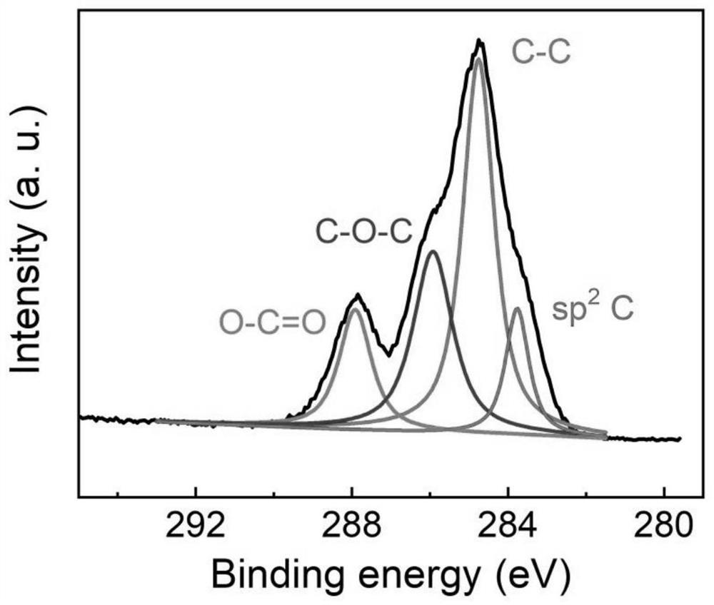
[0030] Sampling ink carbon 2 carries out X-ray photoelectron energy spectrum analysis, the result is as follows figure 2 As shown, it is confirmed that the ink carbon contains more oxygen-containing functional groups.
Embodiment 2
[0032] A preparation method of a humidity micro-generation device based on dust-free paper and ink, comprising the following steps:
[0033] (1) Cut the dust-free paper into small pieces of 6cm*1cm; (2) Soak the cut dust-free paper in ink and let it dry in the air; (3) Drop 0.25ml LiCl solution (5M ) dried at 80°C to form crystals; (4) both ends of the paper were coated with conductive silver paint to isolate water and copper wires; (5) copper wires and paper were bonded with conductive silver paint, and the (6) Except for the part containing LiCl crystals exposed to the air, the rest of the device is sealed with adhesive tape.
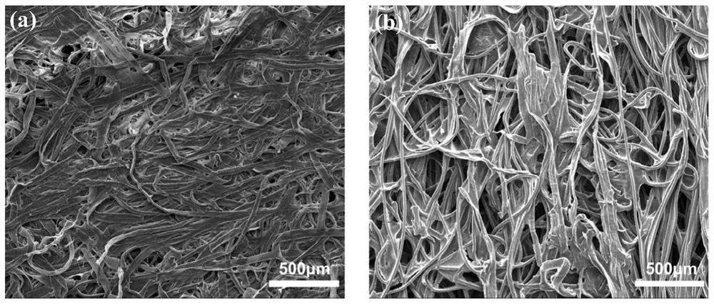
[0034] The dust-free paper after sampling step (1) and the dust-free paper coated with ink in step (2) are respectively sampled for electron microscope scanning, and the results are as follows: figure 1 As shown in (a) and (b), it can be seen from the diagram that the surface of the dust-free paper has a unique porous structure, and the ink carbon is...
Embodiment 3
[0037] A preparation method of a humidity micro-generation device based on dust-free paper and ink, comprising the following steps:
[0038] (1) Cut the dust-free paper into small pieces of 6cm*1cm; (2) Soak the cut dust-free paper in ink and let it dry in the air; (3) Drop 0.25ml LiCl solution (2M ) dried at 80°C to form crystals; (4) both ends of the paper were coated with conductive silver paint to isolate water and copper wires; (5) copper wires and paper were bonded with conductive silver paint, and the (6) Except for the part containing LiCl crystals exposed to the air, the rest of the device is sealed with adhesive tape.
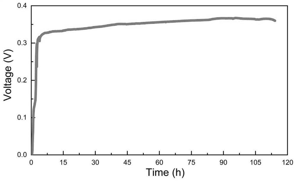
[0039] After the preparation was completed, the whole device was subjected to a performance test at a constant humidity of 50%, and a voltage of 0.26V and a current of 23.8μA were generated.
PUM
 Abstract
Description
Claims
Application Information
 - R&D
- Intellectual Property
- Life Sciences
- Materials
- Tech Scout
- Unparalleled Data Quality
- Higher Quality Content
- 60% Fewer Hallucinations
Browse by: Latest US Patents, China's latest patents, Technical Efficacy Thesaurus, Application Domain, Technology Topic, Popular Technical Reports.
© 2025 PatSnap. All rights reserved.Legal|Privacy policy|Modern Slavery Act Transparency Statement|Sitemap|About US| Contact US: help@patsnap.com


