Adaptive Fault Detection and Isolation Methods for Uncertain Nonlinear Control Systems
A nonlinear control and fault detection technology, applied in general control systems, control/regulation systems, test/monitoring control systems, etc., can solve the problem of adaptive fault detection and isolation methods for uncertain nonlinear control systems, without considering system parameters Uncertainty, single fault type, etc.
- Summary
- Abstract
- Description
- Claims
- Application Information
AI Technical Summary
Problems solved by technology
Method used
Image
Examples
specific Embodiment approach 1
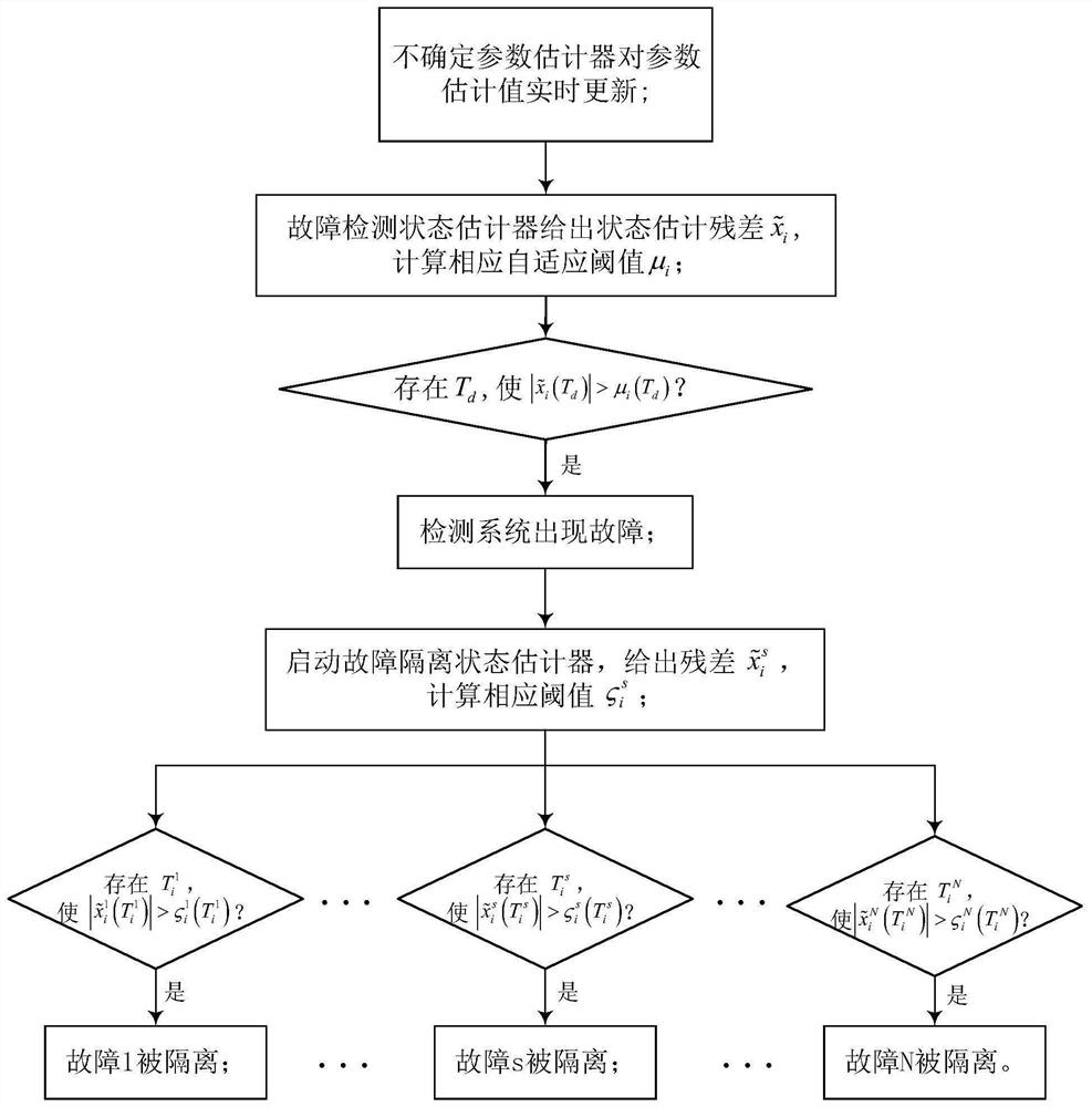
[0054] Specific implementation mode one: combine figure 1 To illustrate this embodiment, the adaptive fault detection and isolation method for an uncertain nonlinear control system includes:
[0055] Step 1: Design an uncertain parameter estimation scheme for the control system model, update the estimated values of uncertain parameters in real time, reduce the influence of parameter uncertainty on fault diagnosis, and improve the sensitivity of the fault detection scheme;
[0056] The control system model is a nonlinear control system containing parameter uncertainty, and its state space expression is:
[0057]
[0058] Among them, x is the n-dimensional state vector of the system; is the first derivative of x, that is, the state space model of the system; θ is an uncertain parameter, f(x,u) and is a known nonlinear function matrix, Δ(x, u, t) represents the nonlinear uncertainty; assuming that the system only has one specific fault in N types of faults (this method ...
specific Embodiment approach 2
[0095] Specific implementation mode two: this implementation mode is different from the specific implementation mode in that the steps described in step one upper bound of for:
[0096] upper bound of for:
[0097]
[0098] Among them, λ m is the largest eigenvalue of matrix A, δ m is the upper bound of the system disturbance, ie |Δ(x,u,t)|≤δ m ;
[0099] The initial value of the parameter adaptive estimation error upper bound is:
[0100]
[0101] Among them, θ max ,θ min are the upper and lower bounds of the uncertain parameter vector modulus, namely θ min ≤|θ|≤θ max .
[0102] Other steps and parameters are the same as those in the first embodiment.
specific Embodiment approach 3
[0103] Specific implementation mode three: the difference between this implementation mode and specific implementation modes one or two is that the steps described in step two Corresponding fault detection adaptive threshold μ i (t), specifically:
[0104]
[0105] Among them, Ψ i (x,u) is a known function row vector the upper bound of L i Represents the state estimator gain of the state estimator (12), t represents the running time of the system, δ im is the upper bound of the disturbance component of the system, ie |Δ i (x,u,t)|≤δ im .
[0106] Other steps and parameters are the same as those in Embodiment 1 or 2.
PUM
 Abstract
Description
Claims
Application Information
 - R&D
- Intellectual Property
- Life Sciences
- Materials
- Tech Scout
- Unparalleled Data Quality
- Higher Quality Content
- 60% Fewer Hallucinations
Browse by: Latest US Patents, China's latest patents, Technical Efficacy Thesaurus, Application Domain, Technology Topic, Popular Technical Reports.
© 2025 PatSnap. All rights reserved.Legal|Privacy policy|Modern Slavery Act Transparency Statement|Sitemap|About US| Contact US: help@patsnap.com


