
Icing real-time monitoring system based on fiber Bragg grating

A technology of fiber Bragg and fiber grating, which is applied in the direction of measuring, measuring force, and measuring device by measuring the change force of the optical properties of the material when it is stressed, and can solve the problems of short service life, electromagnetic interference signals of electronic sensors, instability, etc. problem, to achieve the effect of small size and high sensitivity

Pending Publication Date: 2020-09-18
BEIJING UNIV OF POSTS & TELECOMM +2
View PDF0 Cites 4 Cited by
  • Summary
  • Abstract
  • Description
  • Claims
  • Application Information

AI Technical Summary

Problems solved by technology

Most of the existing on-line monitoring systems for icing on transmission lines are composed of electronic devices. Due to the influence of external conditions, there are still some weaknesses in the existing traditional electronic sensors in our country.
Under strong electromagnetic field conditions, electronic sensors are susceptible to electromagnetic interference and long-distance transmission signals are unstable and have short service life.

Method used


Image

  • Icing real-time monitoring system based on fiber Bragg grating
  • Icing real-time monitoring system based on fiber Bragg grating
  • Icing real-time monitoring system based on fiber Bragg grating

Examples


Embodiment 1

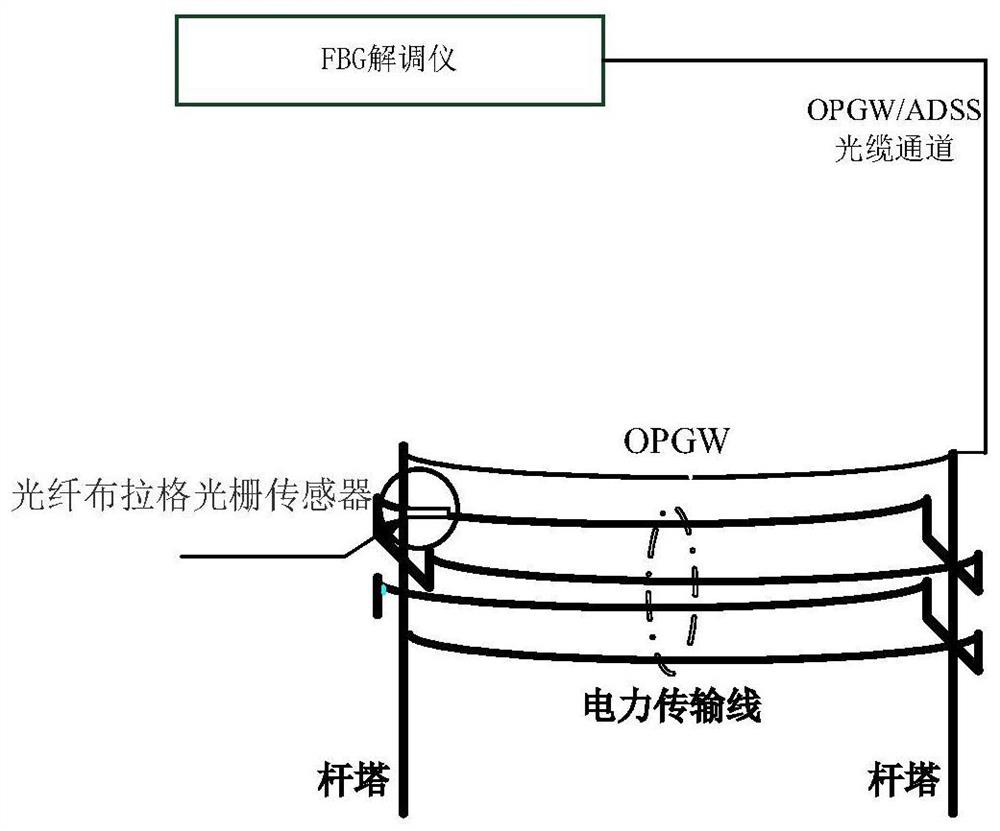
[0054] In order to solve the above problems, the present invention proposes a real-time monitoring system for ice coating based on fiber Bragg gratings, which realizes online real-time monitoring of the thickness of ice coating on OPGW optical cables.

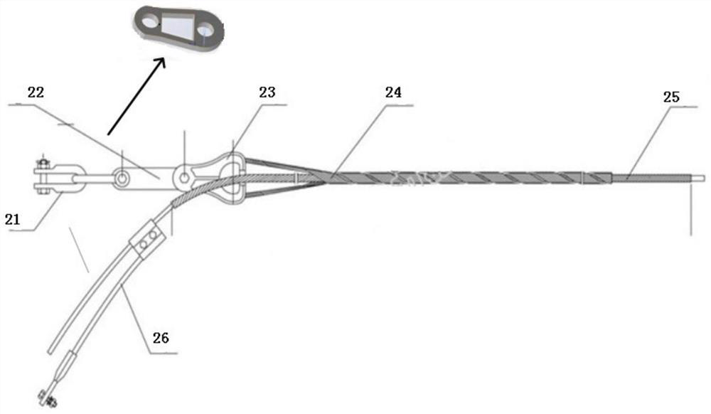
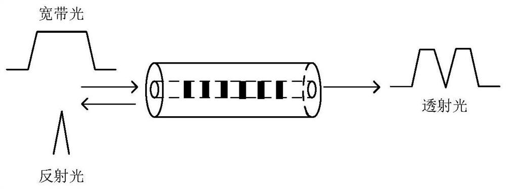
[0055] Such as figure 1 Shown is a schematic diagram of a real-time monitoring system for ice coating based on fiber Bragg gratings. The monitoring system includes OPGW optical cables, fiber Bragg grating sensors, and fiber grating demodulators. The fiber Bragg grating sensors can measure the wavelength deviation caused by the thickness of ice coating. The displacement, so that the real-time measurement of the ice thickness of the optical cable can be realized. Such as figure 2 Shown is a schematic diagram of a system for fiber grating measurement of icing. The PD hanging plate at the connection of the optical cable of the present invention adopts a cantilever beam 22 with a triangular structure, and the two ends of the trian...


PUM


Abstract

The invention provides an icing real-time monitoring system based on a fiber Bragg grating. The icing real-time monitoring system comprises a fiber Bragg grating sensor, a fiber Bragg grating demodulator and an OPGW optical cable. The fiber Bragg grating sensor comprises a fiber Bragg grating FBG1, a fiber Bragg grating FBG2 and a triangular cantilever beam, the fiber Bragg grating FBG1 is pastedon the outer side of the triangular cantilever beam, the fiber Bragg grating FBG2 is pasted on the inner side of the triangular cantilever beam, and the fiber Bragg grating sensor is fixed on the OPGWoptical cable. The fiber Bragg grating demodulator is connected with the fiber Bragg grating sensor and is used for demodulating a wavelength value after the fiber Bragg grating sensor generates thepressure change stress, calculating a composite wavelength offset according to the wavelength value and monitoring the icing thickness in real time.

Description

technical field [0001] The invention relates to the field of optical fiber sensing, in particular to an ice-covered real-time monitoring system based on an optical fiber Bragg grating. Background technique [0002] With the continuous improvement of the power industry's requirements for the safe and stable operation of transmission lines, meteorological factors, seasonal influences, altitude influences, geographical environment influences, line direction influences, and conductors themselves will all lead to icing on the conductors of transmission lines. Under the action of wind, ice-coated conductors will cause galloping, deicing and jumping accidents, and insulator string ice flashing accidents. When there is a large amount of ice on the line, the overload phenomenon will cause the mechanical and electrical failure of the overhead transmission line, and the unbalanced tension on both sides of the tower will increase. , not only caused a lot of inconvenience and difficulti...

Claims


Application Information

Patent Timeline
Patent Type & Authority Applications(China)
IPC IPC(8): G01L1/24G01B11/06
CPCG01B11/0625G01L1/246
Inventor 张治国王潇潇颜哲昊李路明肖子洋陈兴陈硕
Owner BEIJING UNIV OF POSTS & TELECOMM
Learn More