Electromagnetic induction de-icing method and device
A technology of electromagnetic induction and electromagnetic induction layer, which is applied in the direction of induction heating, cable installation, electrical components, etc., can solve the problem of limited deicing range and achieve the effect of saving manpower, small size and light weight
- Summary
- Abstract
- Description
- Claims
- Application Information
AI Technical Summary
Problems solved by technology
Method used
Image
Examples
Embodiment 1
[0022] An electromagnetic induction melting ice method described in this embodiment is to set at least one insulating ring at the place where the power line is likely to be covered with ice, and an electromagnetic induction ring is arranged outside each insulating ring, and the electromagnetic induction ring is made of electromagnetic induction heating material production. The electromagnetic induction ring is a ring that can be opened and closed, and is made of electromagnetic induction material. A diaphragm pressure sensor is arranged outside the electromagnetic induction ring, and the pressure sensor is connected with an operating mechanism for controlling the opening and closing of the electromagnetic induction ring. When the ice coating on the transmission line reaches a preset thickness, the pressure sensor provides a signal to the operating mechanism, and the operating mechanism closes the electromagnetic induction loop, which then generates heat to melt the ice coating...
Embodiment 2
[0024] An electromagnetic induction melting ice method described in this embodiment is to set at least one insulating ring on the place where the power line is prone to icing, and an electromagnetic induction layer is arranged outside each insulating ring, and the electromagnetic induction layer is an openable , Combined coil, the electromagnetic induction coil is made of electromagnetic induction heating material. A pressure sensor is arranged outside the electromagnetic induction layer, and the pressure sensor is connected with the operating mechanism that controls the opening and closing of the electromagnetic induction coil; The magnetic induction coil is closed, and the electromagnetic induction ring then generates heat to melt the ice; as the ice melts and becomes thinner or disappears, the pressure sensor senses the pressure signal and transmits the signal to the operating mechanism, and the electromagnetic induction coil turns on and stops heating. The ice melting job ...
Embodiment 3
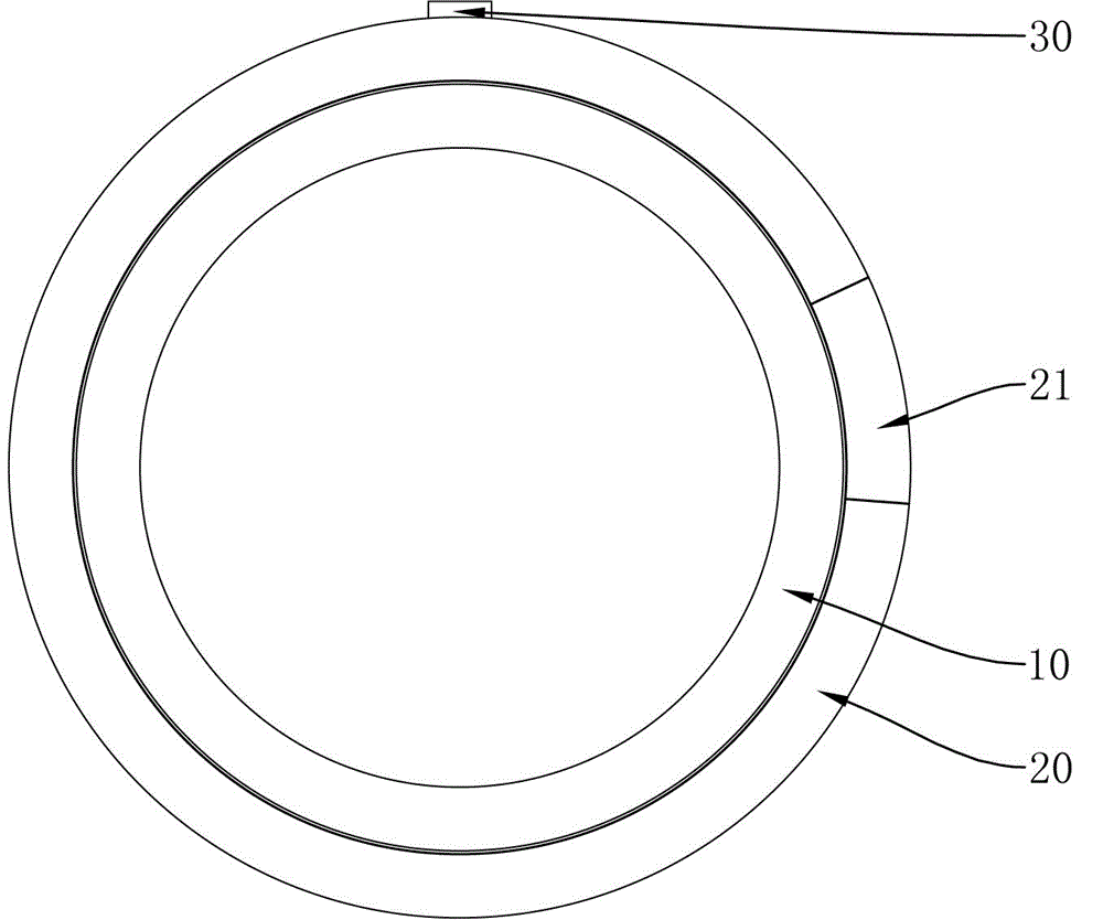
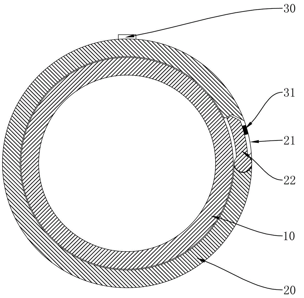
[0026] The electromagnetic induction ice-melting device of an embodiment of the present invention see figure 1 and figure 2 . The electromagnetic induction ice melting device includes an insulating ring 10, an electromagnetic induction ring is arranged on the outer layer of the insulating ring 10, and a pressure sensor 30 is arranged outside the electromagnetic induction ring.
[0027] The electromagnetic induction ring is made of electromagnetic induction heating material, including a split ring 20 and a metal shrapnel 22. One end of the metal shrapnel 22 is hinged to the split ring 20, and the other end can rotate around the hinge. When the fixed end of the metal shrapnel overlaps When connected to the split ring 20, the split ring 20 and the metal shrapnel 22 form a closed ring.
[0028] The opening of the split ring 20 is provided with an insulating protective shell 31, which completely wraps the metal dome 22, prevents rainwater from forming ice coating between the met...
PUM
 Abstract
Description
Claims
Application Information
 - R&D
- Intellectual Property
- Life Sciences
- Materials
- Tech Scout
- Unparalleled Data Quality
- Higher Quality Content
- 60% Fewer Hallucinations
Browse by: Latest US Patents, China's latest patents, Technical Efficacy Thesaurus, Application Domain, Technology Topic, Popular Technical Reports.
© 2025 PatSnap. All rights reserved.Legal|Privacy policy|Modern Slavery Act Transparency Statement|Sitemap|About US| Contact US: help@patsnap.com


