Intelligent efficient steady-state one-time heat exchange type waste heat recycling machine

A one-time, recovery machine technology, applied in the direction of heat exchanger type, heat exchanger, indirect heat exchanger, etc., can solve the problems of short residence time of flue gas, large diameter of flue gas outlet, and reduce heat utilization, etc., to achieve Eliminate cleaning, prolong service life, and ensure the effect of heat utilization

Inactive Publication Date: 2020-09-18
赵国栋
View PDF0 Cites 4 Cited by
  • Summary
  • Abstract
  • Description
  • Claims
  • Application Information

AI Technical Summary

Problems solved by technology

[0004] The purpose of the present invention is to provide an intelligent, high-efficiency, steady-state disposable heat-exchanging waste heat recovery machine to solve the problem that the existing heat-exchanging waste heat recovery machine proposed in the background technology is too large in the use of the flue gas outlet. If the residence time is too short, it is easy to cause heat to flow out directly at the flue gas outlet, which reduces the problem of heat utilization

Method used


Image

  • Intelligent efficient steady-state one-time heat exchange type waste heat recycling machine
  • Intelligent efficient steady-state one-time heat exchange type waste heat recycling machine
  • Intelligent efficient steady-state one-time heat exchange type waste heat recycling machine

Examples


Embodiment 1

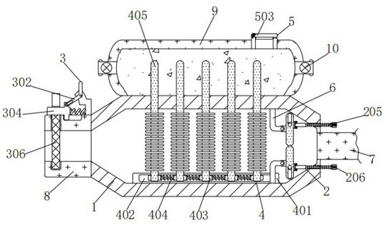
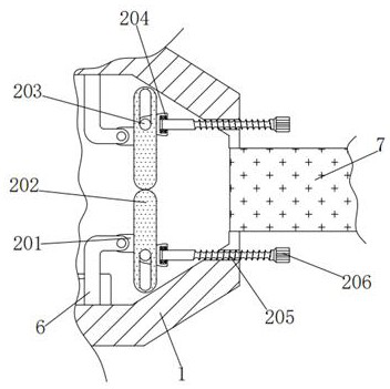
[0036] An intelligent, high-efficiency, steady-state disposable heat-exchanging waste heat recovery machine, comprising a furnace body 1, a support 6 is fixedly connected to the upper, lower and right sides of the inner wall of the furnace body 1, and an adjustment mechanism 2 is installed on the right side of the two supports 6. Mechanism 2 comprises short plate 201, vertical plate 202, first circular plate 203, triangular plate 204, threaded rod 205 and handle 206, and the fronts of two short plates 201 are connected with the rear end face right side of two supports 6 respectively, short The plate 201 is forced to rotate through the pin shaft on the right side of the rear end of the bracket 6. The right sides of the two short plates 201 are fixedly connected to the left side of the vertical plate 202, and the inner walls of the two vertical plates 202 are respectively connected to the first circular plate. The outer wall of 203 is slidingly engaged, and the first circular pla...

Embodiment 2

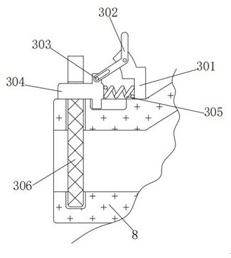
[0038] As an option, see figure 1 , 3 And 4, intelligent high-efficiency steady-state disposable heat exchange waste heat recovery machine, the left side of the furnace body 1 is connected with a thick tube 8, and the top of the thick tube 8 is installed with a fixing mechanism 3, and the fixing mechanism 3 includes a curved plate 301 and a curved plate 302 , the second circular plate 303, the protruding rod 304, the first spring 305 and the filter screen 306, the bottom of the curved plate 301 is fixedly connected with the top right side of the thick pipe 8, and the top of the curved plate 301 rotates with the inner wall of the curved plate 302 Connected, the curved plate 302 is forced to rotate through the pin shaft above the front of the curved plate 301, the groove under the front of the curved plate 302 is slidingly engaged with the outer wall of the second circular plate 303, and the second circular plate 303 is forced to pass through the curved plate 302 The groove und...

Embodiment 3

[0041] As an option, see figure 1 and 5, an intelligent high-efficiency steady-state disposable heat exchange waste heat recovery machine, a heat transfer mechanism 4 is installed at the bottom of the inner wall of the furnace body 1, and the heat transfer mechanism 4 includes a long plate 401, a chute 402, a block 403, a second spring 404 and a spiral fin Sheet 405, the bottom of the long plate 401 is fixedly connected with the bottom of the inner wall of the furnace body 1, the inner wall of the long plate 401 is processed with a chute 402, and the inner wall of the chute 402 is equidistantly processed with a block 403, and the block 403 is forced to pass through the chute 402 The inner walls of the blocks 403 slide left and right, and the outer walls of multiple blocks 403 are fixedly connected with second springs 404. After the blocks 403 are forced to move, they are rebounded by the second springs 404. The bottom of the rear end of 405 is fixedly connected, and the top o...


PUM


Abstract

The invention discloses an intelligent efficient steady-state one-time heat exchange type waste heat recycling machine. The intelligent efficient steady-state one-time heat exchange type waste heat recycling machine comprises a furnace body, wherein brackets are fixed connected to the upper and lower right sides of the inner wall of the furnace body, adjusting mechanisms are mounted on right sidesof the two brackets, each adjusting mechanism comprises a short plate, a vertical plate, a first round plate, a triangular plate, a threaded rod and a grip, front sides of the two short plates are rotationally connected with the right sides of the rear end surfaces of the two brackets respectively, and the right sides of the two short plates are fixedly connected with the left sides of the vertical plates respectively. According to the intelligent efficient steady-state one-time heat exchange type waste heat recycling machine, the adjusting mechanisms control the vertical plates to rotate toadjust size of a flue gas outlet, flue gas is prevented from flowing out directly, and heat utilization is guaranteed; second springs in a heat transfer mechanism protect square blocks, so that shaking of heat transfer pipes is weakened, the heat transfer pipes are prevented from being damaged, the service life is prolonged, a filter screen in a fixing mechanism filters the flue gas, so that the heat transfer pipes are prevented from getting dirty, troubles in cleaning are omitted, normal use is ensured, practicability is improved, and popularization is facilitated.

Description

technical field [0001] The invention relates to the technical field of an intelligent, high-efficiency, steady-state, disposable heat-exchange waste heat recovery machine, in particular to an intelligent, high-efficiency, steady-state, one-time heat-exchange waste heat recovery machine. Background technique [0002] The heat exchange type waste heat recovery machine is mainly used for the following purposes to recover waste heat and avoid environmental pollution caused by waste gas or waste liquid thermal discharge process. Recovering the heat produced by the equipment can optimize the use environment of the equipment. [0003] Existing heat-exchanging waste heat recovery machines are used with too large flue gas outlet caliber, and the flue gas residence time is too short, which easily causes heat to flow out directly at the flue gas outlet, reducing heat utilization, and the heat transfer tube (spiral fin sheet) without protection, the flue gas will cause shaking, easy to ...

Claims


Application Information

Patent Timeline
Patent Type & Authority Applications(China)
IPC IPC(8): F23J15/02F23J15/06F28D21/00F28F27/02F16F15/067
CPCF16F15/067F23J15/025F23J15/06F28D21/0014F28F27/02Y02E20/30
Inventor 不公告发明人
Owner 赵国栋
Why Eureka
Try Eureka