
A kind of linkage sealing damper

A sealed, damper technology, used in lift valves, valve devices, engine components, etc., can solve problems such as hidden dangers in the sealing effect and no sealing protection structure.

Active Publication Date: 2021-12-14
江苏磊霆精密新材料有限公司
View PDF0 Cites 0 Cited by
  • Summary
  • Abstract
  • Description
  • Claims
  • Application Information

AI Technical Summary

Problems solved by technology

[0002] The damper is a regulating valve with a relatively simple structure, which is usually used to cut off or throttle the air flow in the pipeline; the existing damper generally includes a valve body, a valve plate, a driving rod, and a sealing ring; the sealing ring is installed on the valve body Inside, the valve plate is sealed or separately connected to the sealing ring inside the valve body, and then the driving rod extends downward from the upper end of the valve body to the upper end of the valve plate inside the valve body, by rotating the driving rod, the driving rod drives the valve plate to rotate, thereby It can complete the opening and closing or separation process around the outer side of the valve plate and the inner wall of the inner sealing ring of the valve body; but the above air valve structure has only one valve plate as the sealing part, and there is no multiple sealing protection structure, so that the sealing effect has hidden dangers

Method used


Image

  • A kind of linkage sealing damper
  • A kind of linkage sealing damper
  • A kind of linkage sealing damper

Examples


Embodiment Construction

[0019] The content of the present invention will be further described in detail below in conjunction with the accompanying drawings.

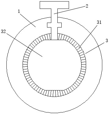
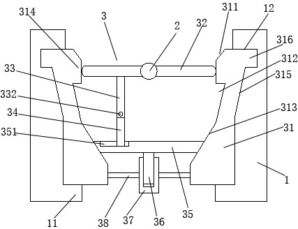
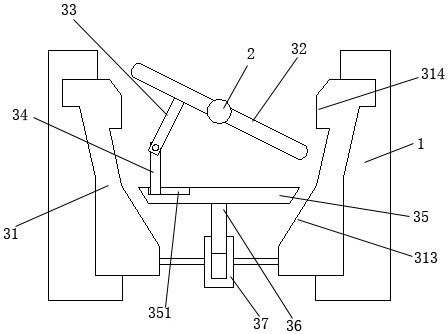
[0020] Such as Figures 1 to 5 As shown, a interlocking sealing air valve includes a valve body 1, a driving rod 2, and an interlocking sealing mechanism 3; the interlocking sealing mechanism 3 includes a sealing ring 31, an inner end closing plate 32, and an outer end closing plate 35 , rotating rod 33, sliding telescopic rod 34, guide column 36, guide cylinder 37, connecting rod 38; described sealing ring 31 is installed in the inside of valve body 1; the inner side of described sealing ring 31 inner end is provided with inner sealing protruding ring 314; the inside of the outer end of the sealing ring 31 is provided with a tapered sealing ring surface 313; the tapered sealing ring surface 313 has a conical structure with a large inner end and a small outer end; the outer sealing plate 35 is flat The conical structure of the body; the inner ...


PUM


Abstract

The invention discloses a linkage sealing air valve, which comprises a valve body, a driving rod, and a linkage sealing mechanism; Rod, guide column, guide cylinder, connecting rod; the invention realizes the rotary separation of the inner end closure plate or abuts against the inner sealing convex ring through the rotation of the drive rod, and simultaneously realizes the translational separation or abutment of the outer end closure plate Connected to the tapered sealing ring surface, thus realizing the simultaneous double separation or sealing connection effect.

Description

technical field [0001] The invention relates to a linkage sealing air valve. Background technique [0002] The damper is a regulating valve with a relatively simple structure, which is usually used to cut off or throttle the air flow in the pipeline; the existing damper generally includes a valve body, a valve plate, a driving rod, and a sealing ring; the sealing ring is installed on the valve body Inside, the valve plate is sealed or separately connected to the sealing ring inside the valve body, and then the driving rod extends downward from the upper end of the valve body to the upper end of the valve plate inside the valve body, by rotating the driving rod, the driving rod drives the valve plate to rotate, thereby It can complete the opening and closing or separation process around the outer side of the valve plate and the inner wall of the inner sealing ring of the valve body; but the above air valve structure has only one valve plate as the sealing part, and there is n...

Claims


Application Information

Patent Timeline
Patent Type & Authority Patents(China)
IPC IPC(8): F16K1/226F16K1/32F16K1/44
CPCF16K1/223F16K1/226F16K1/2263F16K1/32F16K1/44
Inventor 朱银德
Owner 江苏磊霆精密新材料有限公司
Learn More