Device for quickly screwing steel bar splicing sleeve

A technology of connection and sleeve, applied in the direction of structural elements, building components, building reinforcements, etc., can solve the problems of unsuitable connection of two sections of steel mesh cages, small wrench rotation angle, high labor intensity, etc., to achieve clamping or It is convenient and fast to loosen the workpiece, convenient and fast to clamp the workpiece, and overcome the troublesome effect of connecting the sleeve

Inactive Publication Date: 2020-09-18
ROAD & BRIDGE INT +2
View PDF6 Cites 0 Cited by
  • Summary
  • Abstract
  • Description
  • Claims
  • Application Information

AI Technical Summary

Problems solved by technology

Although this method is relatively simple, it has defects such as high labor intensity and low efficiency.
[0003] For this reason, "CN208960871U" and "CN210189680U" respectively disclose two types of portable rebar fast connecting devices with different structures. Although the labor intensity is reduced and the work efficiency is improved, the above-mentioned patents can only realize the continuation of two sections of horizontal steel bars; It is not suitable for the connection of two sections of steel mesh cages, so the method of screwing with a wrench is still required
There are defects such as narrow operating space, small turning angle of the wrench, low efficiency, and high requirements for the operator's technical proficiency

Method used


Image

  • Device for quickly screwing steel bar splicing sleeve
  • Device for quickly screwing steel bar splicing sleeve
  • Device for quickly screwing steel bar splicing sleeve

Examples


Embodiment Construction

[0027] The present invention will be further described below in conjunction with the accompanying drawings and specific embodiments.

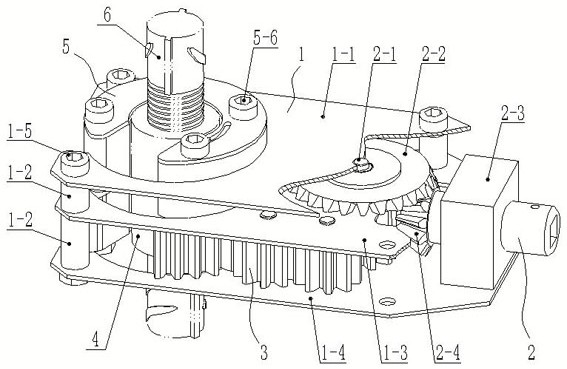
[0028] Such as Figure 1-12 As shown: the frame 1 is composed of an upper plate 1-1, a middle plate 1-4, a bottom plate 1-5 arranged from top to bottom, and four upper plates supported between the upper plate 1-1 and the middle plate 1-4. The spacer 1-2 is composed of four lower spacers 1-3 supported between the middle plate 1-4 and the bottom plate 1-5; and passes through the upper plate 1-1 and the upper spacer 1 respectively from top to bottom -2. The four frame connecting bolts 1-6 of the middle plate 1-4, the lower spacer 1-3 and the bottom plate 1-5, and the nuts matched with the connecting bolts 1-6 of each frame (not shown in the figure) The connection is fixed. There are positioning holes on the corresponding positions of the upper plate 1-1, the middle plate 1-4 and the bottom plate 1-5, and the left sides of the three plates are pr...


PUM


Abstract

The invention discloses a device for quickly screwing a steel bar splicing sleeve. The device for screwing the splicing sleeve can realize the butt joint of steel bar cages, and comprises a rack, a chuck, a transmission mechanism and a driving mechanism, wherein the rack (1) is composed of an upper plate (1-1), a middle plate (1-4), a bottom plate (1-5) and spacer sleeves; the upper plate, the middle plate and the bottom plate are each provided with a C-shaped positioning hole (1-7); a clamping mechanism (5) is composed of a chuck body (5-1) matched with the C-shaped positioning holes (1-7), C-shaped plates (5-2) positioned on the two end faces of the chuck body, and a roller (5-4) positioned in the chuck body; each C-shaped plate (5-2) is provided with a guide groove (5-3); the transmission mechanism (3) is composed of an open gear (3-3) fixedly connected with the chuck (5), two idle gear sets engaged with the open gear, and a driving gear (3-1) engaged with the two idle gear sets; and the driving mechanism (2) is composed of a driven bevel gear (2-2) and a driving bevel gear (2-4).

Description

technical field [0001] The invention relates to a screwing device for a connecting sleeve, in particular to a device for quickly screwing a connecting sleeve for steel bars, which belongs to the connecting device for steel bars. Background technique [0002] The use of extension sleeves to realize the connection of two sections of steel bars is a new process of steel bar connection after the binding process and welding process. It is widely used in the construction industry because of its high joint strength, fast connection speed, steel saving and many other advantages. use. Tools such as wrench or pipe wrench are usually used to screw the connecting sleeve or reinforcing bar at present, so that the reinforcing bars at both ends are respectively screwed into the connecting sleeve to realize docking. Although this method is relatively simple, it has defects such as high labor intensity and low efficiency. [0003] For this reason, "CN208960871U" and "CN210189680U" respecti...

Claims


Application Information

Patent Timeline
Patent Type & Authority Applications(China)
IPC IPC(8): E04G21/12E04C5/16
CPCE04C5/165E04G21/122
Inventor 韩敏慧杨兴龙粱玉岭韩志嵘杨阳夏五四左宇欢杨再华王雄飞杨正伦
Owner ROAD & BRIDGE INT
Why Eureka
Try Eureka