
Novel anti-collision column

A new type of anti-collision column technology, applied in the direction of floors, coverings/linings, buildings, etc., can solve the problems of easy local damage, high strength and rigidity requirements, etc., to achieve good protection, improve strength and rigidity, and reduce the possibility of sexual effect

Pending Publication Date: 2020-09-18
GUIZHOU ELECTRIC POWER DESIGN INST
View PDF0 Cites 0 Cited by
  • Summary
  • Abstract
  • Description
  • Claims
  • Application Information

AI Technical Summary

Problems solved by technology

[0002] In industrial and civil plants, especially those involving frequent machinery and vehicles, such as pre-treatment workshops and sludge treatment workshops in waste-to-energy plants, due to the frequent operations of machinery and vehicles, mechanical The collision of the vehicle and the anti-collision method of the factory building column is to set the wrap angle at the corner of the column to prevent the damage and destruction of the column in the case of impact. One disadvantage of this conventional method is that due to the large load of machinery and vehicles, Considering that the column directly bears the impact load, the strength and stiffness of the column itself are required to be high, and it is easy to cause local damage

Method used


Image

  • Novel anti-collision column
  • Novel anti-collision column
  • Novel anti-collision column

Examples


Embodiment 1

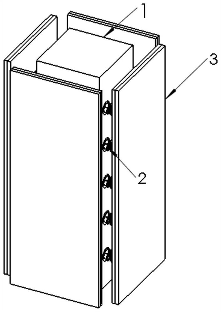
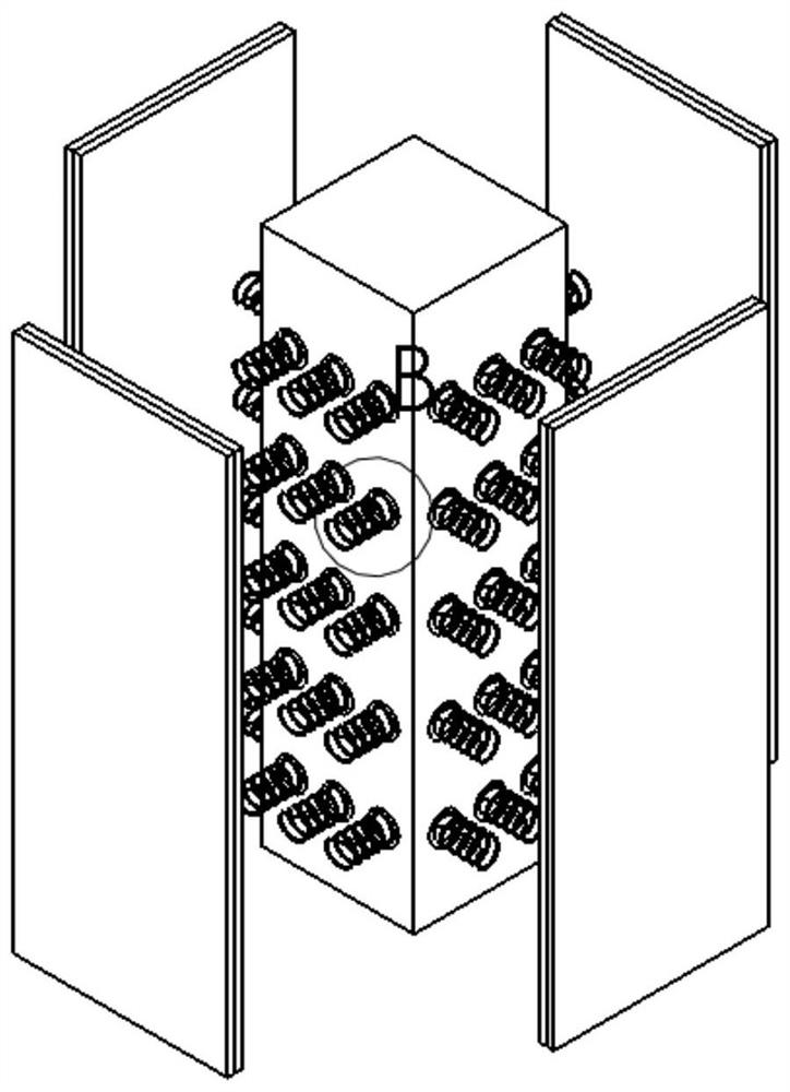
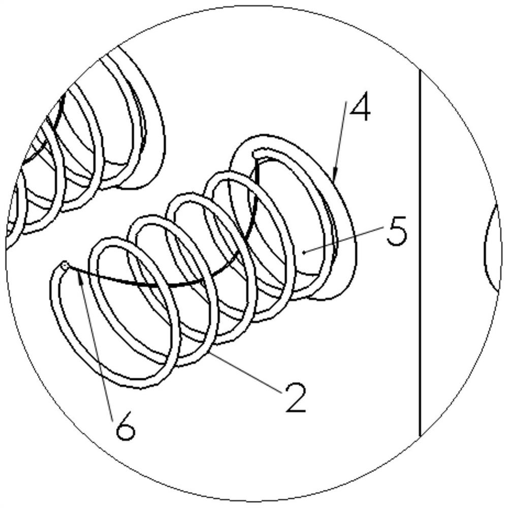
[0030] Example 1: Reference Figure 1 to Figure 5 , A new type of anti-collision pillar, including: a square column 1; also including: an anti-collision plate 3, the outer side of the anti-collision plate 3 is a rubber layer 301, the anti-collision plate 3 includes four, the anti-collision plate 3 and the square The side of the column 1 is matched; the compression spring 2, the anti-collision plate 3 is connected to the surrounding surface of the square column 1 through the compression spring 2, and the two ends of the compression spring 2 are respectively fixedly connected to the inner surface of the anti-collision plate 3 and the square column 1 In between, the compression springs 2 include more than three, and the compression springs 2 are evenly distributed on the inner surface of the anti-collision board 3.

[0031] Further, the inner surface of the anti-collision board 3 is a hard board 302.

[0032] Furthermore, it further includes: an annular embedded part 4 which is embed...


PUM


Abstract

The invention discloses a novel anti-collision column which comprises a square column body and further comprises four anti-collision plates and three or more compressed springs. The outer side surfaceof each anti-collision plate is a rubber layer, the anti-collision plates are matched with the side surface of the square column, the anti-collision plates are connected to the peripheral surface ofthe square column body through the compressed springs, the two ends of the compressed springs are fixedly connected between the inner side surfaces of the anti-collision plates and the square column body correspondingly, and the compressed springs are uniformly distributed on the inner side surfaces of the anti-collision plates. The problems that in the prior art, the requirements for the strengthand the rigidity of the column are high, and local damage is likely to cause are solved.

Description

Technical field [0001] The invention relates to the technical field of anti-collision pillars, in particular to a new type of anti-collision pillar. Background technique [0002] In industrial and civil workshops, especially workshops that involve frequent operations of machinery and vehicles, such as pre-treatment workshops and sludge treatment workshops in waste-to-energy plants, due to the frequent operations of machinery and vehicles, machinery should be considered in conventional plant columns. In the case of vehicle collision, the conventional method of anti-collision for plant columns is to set wrap angles at the corners of the columns to prevent damage and destruction of the columns in the event of a collision. This conventional method has a disadvantage that the load of machinery and vehicles is very large. Considering that the column directly bears the impact load, the strength and rigidity of the column itself are required to be high, and it is easy to cause local dama...

Claims


Application Information

Patent Timeline
IPC IPC(8): E04F13/073E04F13/075
CPCE04F13/0736E04F2290/044
Inventor 汪俊虎张凡高原李念斌陈默然易金刚
Owner GUIZHOU ELECTRIC POWER DESIGN INST
Learn More