A device for punching holes in a building wall and a method for using the same

A punching device and technology for building walls, applied in the field of construction machinery, can solve the problems of manual manual punching, hole punching, high density, etc., and achieve the effects of preventing environmental pollution, improving punching depth, and ensuring punching quality.

Active Publication Date: 2022-05-24
萧县威辰机电工程设备有限公司
View PDF12 Cites 0 Cited by
  • Summary
  • Abstract
  • Description
  • Claims
  • Application Information

AI Technical Summary

Problems solved by technology

[0002] At present, most of the buildings in our country are reinforced concrete walls. While people are increasingly pursuing high-quality life, they also have huge requirements for people's living. Not only do they require complete functions, but they also propose changes in aesthetics. To meet the aesthetics of the building, the wall surface will be decorated and remodeled. During the remodeling process, workers mainly rely on the workers to hold the punching machine to punch holes manually. Although this is greatly conducive to the convenient and fast punching operation, there are The problem is that due to the high hardness of the building wall and the uneven density, the eccentricity of the drill bit may affect the orientation of the hole when drilling, and it is also easy to align the drill bit with the wall only by manual experience. The hole is crooked, which greatly affects the quality of the hole and the speed of the hole
[0003] The Chinese patent with the patent number CN201710369780.0 in the prior art discloses a building wall punching device, including a walking structure and a punching driving structure installed above the walking structure. The first sliding groove, the top end surface on the right side of the punching drive structure is fixed with a punching support member, and the first threaded rod is extended left and right in the first sliding groove, and the first threaded rod is threaded and connected with the first sliding rod extending from the top. The sliding block outside the top end face of the groove, the first cavity is provided in the punching driving structure on the right side of the first sliding groove, the punching driving structure on the right side of the first cavity is provided with a second cavity, and the first cavity The bottom is provided with a second sliding groove, and a second threaded rod is extended left and right in the second sliding groove, and the second threaded rod is threaded and connected with a guide sliding block whose top extends into the first cavity. This invention can realize automatic deep drilling. hole and dust collection work, which improves work efficiency and prevents environmental pollution caused by dust; however, the device occupies a large area and is not suitable for walls with narrow spaces. Manual punching is still required

Method used


Image

  • A device for punching holes in a building wall and a method for using the same
  • A device for punching holes in a building wall and a method for using the same
  • A device for punching holes in a building wall and a method for using the same

Examples


Embodiment 1

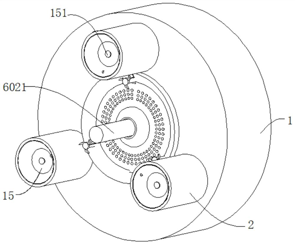
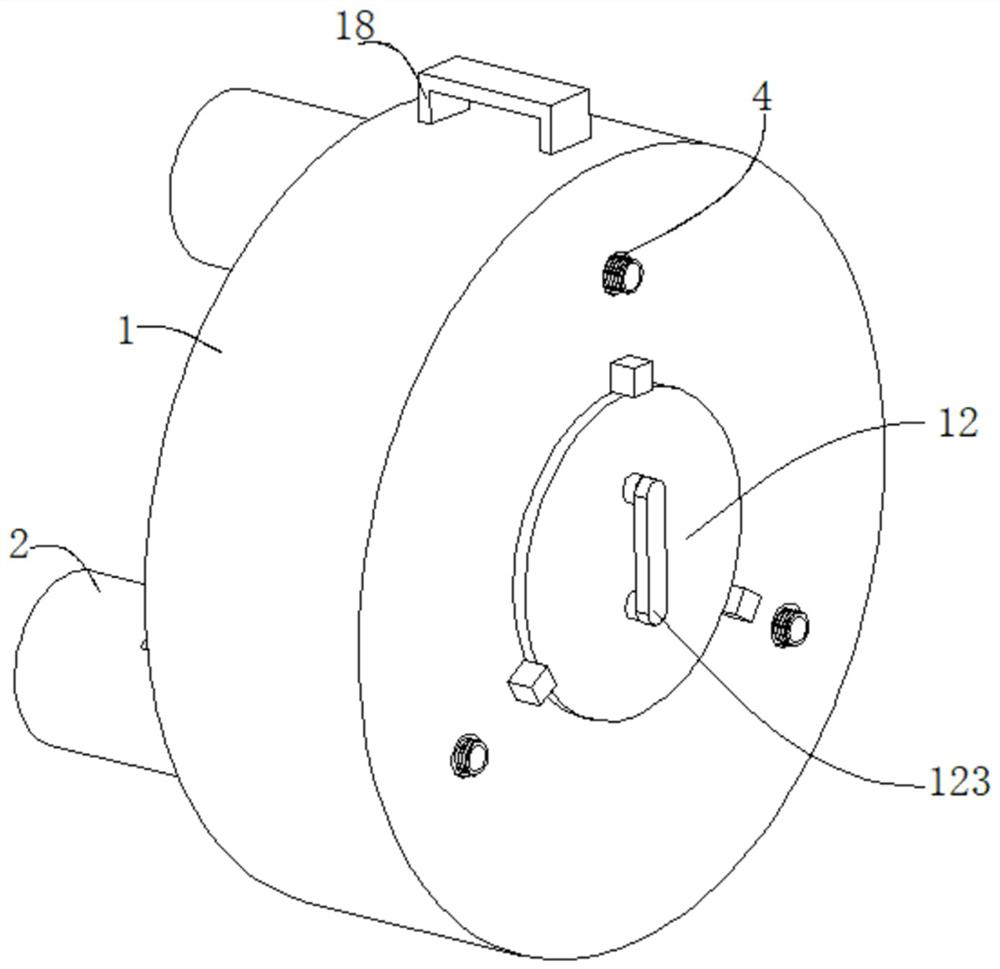
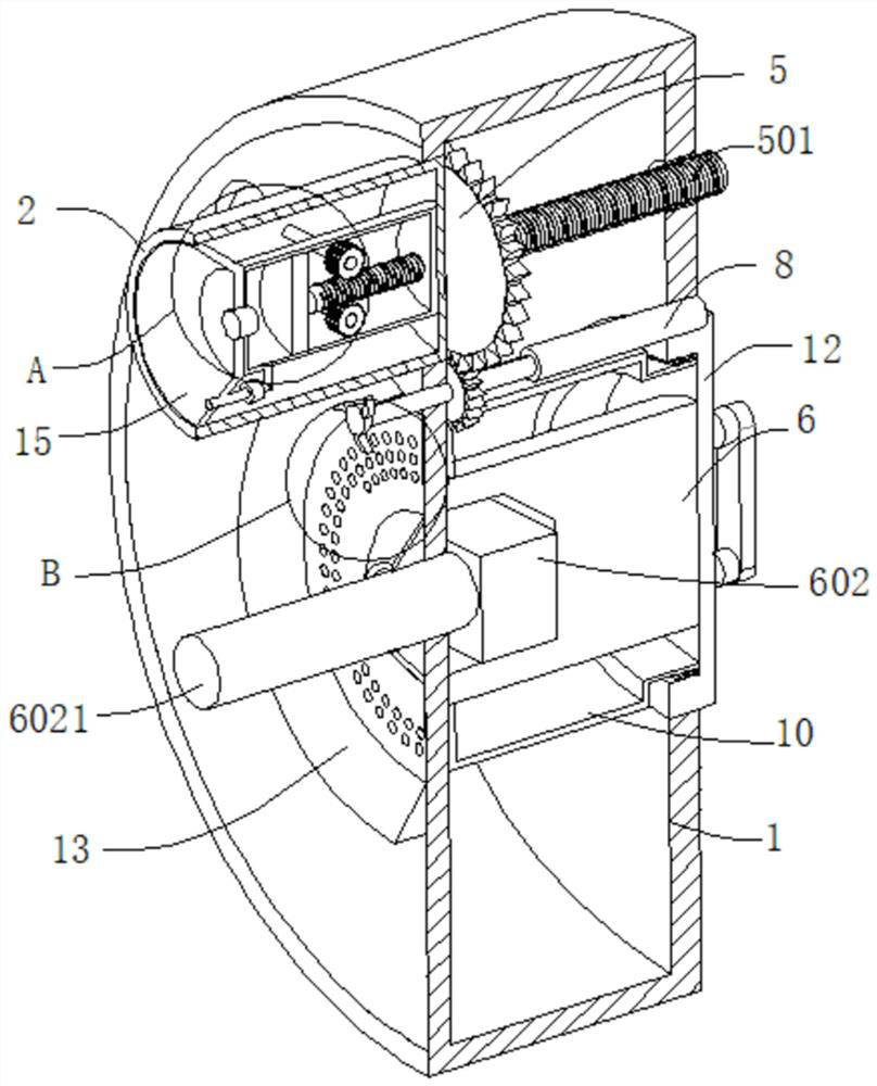
[0037] refer to Figure 1-8 , a construction wall punching device, comprising a machine base 1, the outer wall of the machine base 1 is movably connected with three fixed pipes 2, the inner wall of each fixed pipe 2 is fixedly connected with a sleeve 3, and the inner wall of the sleeve 3 is connected with a fixing mechanism, The outer wall of the base 1 is connected with a second motor, the output end of the second motor is connected with a rotating rod 8, the outer wall of the rotating rod 8 is connected with a second gear 7, the second gear 7 is rotatably connected to the inner wall of the base 1, and the second gear 7 The outer wall is meshed with a first gear 5, the first gear 5 is rotatably connected to the outer wall of the fixed pipe 2, the outer wall of the first gear 5 is connected with a threaded rod 501, and the outer wall of the machine base 1 is drilled with a threaded hole 4 matched with the threaded rod 501, The inner wall of the machine base 1 is connected with a...

Embodiment 2

[0040] refer to image 3 , Figure 4 and Image 6 , a construction wall punching device, basically the same as Embodiment 1, further, the fixing mechanism includes a suction cup 15, the suction cup 15 is fixedly connected to the outer wall of the sleeve 3, the suction cup 15 is placed inside the fixed pipe 2, the sleeve A first one-way valve 151 is connected between the pipe 3 and the suction cup 15, an exhaust pipe 16 is connected to the outer wall of the casing 3, the end of the exhaust pipe 16 away from the casing 3 extends into the suction cup 15, and the outer wall of the exhaust pipe 16 is connected with an exhaust pipe 16. The second one-way valve 161, the inner wall of the sleeve 3 is slidably connected to a piston 301, the outer wall of the piston 301 is connected to a worm 3011, the outer wall of the worm 3011 is engaged with a first worm wheel 3012, the outer wall of the first worm wheel 3012 is connected to a rotating shaft 3013, and the rotating shaft 3013 The e...

Embodiment 3

[0043] refer to Figure 1-8 , a construction wall punching device, which is basically the same as Embodiment 1. Further, a cover body 12 is detachably connected to the machine base 1, a handle 123 is connected to the outer wall of the cover body 12, and the inner wall of the cover body 12 is fixedly provided with The inner thread 121, the outer wall of the annular plate 10 is fixed with an outer thread 122 that matches the inner thread 121; the base 1 is threadedly connected with the cover body 12, which is convenient for discharging the collected dust and avoids too much dust in the dust suction chamber, which affects the dust collection effect.

[0044] Both sides of the outer wall of the machine base 1 are connected with grips 18; by arranging the grips 18 on both sides of the machine base 1, the workers can hold the grips and further reduce the vibration generated during drilling.

[0045] The invention also discloses a method for using the perforating device for a buildi...


PUM


Abstract

The invention discloses a building wall punching device and an application method thereof, which belong to the technical field of construction machinery. A device for punching holes in a building wall, comprising a machine base, three fixed pipes are movably connected to the outer wall of the machine base, a casing is fixedly connected to the inner wall of each fixed pipe, the inner wall of the casing is connected to a fixing mechanism, and the outer wall of the machine base is connected to a second Motor, the output end of the second motor is connected with a rotating rod, the outer wall of the rotating rod is connected with a second gear, the second gear is connected with the inner wall of the machine base in rotation, the outer wall of the second gear is engaged with the first gear, and the first gear is connected with the The outer wall of the fixed pipe is connected with a threaded rod on the outer wall of the first gear; the present invention can artificially assist the drilling of a wall with a small outer space, so that the three fixed pipes are fixed on the wall and relatively retracted into the machine base, ensuring that the drill bit Stable feed during drilling, avoiding drill bit deviation during the drilling process, thereby ensuring the drilling quality.

Description

technical field [0001] The invention relates to the technical field of construction machinery, in particular to a perforating device for a building wall and a method for using the same. Background technique [0002] At present, most of the buildings in our country are reinforced concrete walls. While people are increasingly pursuing a high-quality life, they also have huge requirements for people's living. They not only require complete functions, but also propose changes in aesthetics. To meet the aesthetics of the building, the wall will be decorated and transformed. During the transformation process, it is mainly dependent on the workers to hold the punching machine for manual punching. Although this is greatly beneficial to the convenient and quick punching operation, there are some disadvantages. The problem is that due to the high hardness of the building wall and the possible uneven density, the drilling may cause the eccentricity of the drill bit to affect the orient...

Claims


Application Information

Patent Timeline
Patent Type & Authority Patents(China)
IPC IPC(8): B28D1/14B28D7/02B28D7/00
CPCB28D1/14B28D7/02B28D7/00
Inventor 柳松
Owner 萧县威辰机电工程设备有限公司
Why Eureka
Try Eureka