
Electric power cabinet with built-in dehumidification mechanism

A technology of power cabinets and power cabinets, which is applied in the cooling/ventilation of substations/switchgears, electrical components, substations/power distribution device shells, etc., and can solve the problems of excessive humidity in power cabinets, hidden dangers of power safety, and easy water accumulation, etc. problems, to achieve the effect of convenient use, not easy to accumulate water, and reduce the probability of accidents

Inactive Publication Date: 2020-09-15
苏州八度阳光智能科技有限公司
View PDF0 Cites 0 Cited by
  • Summary
  • Abstract
  • Description
  • Claims
  • Application Information

AI Technical Summary

Problems solved by technology

[0005] The object of the present invention is to provide a power cabinet with a built-in dehumidification mechanism, including a power cabinet and a dehumidification device. The lower side of the flow canopy makes the circulation air path in an S-shaped direction. In seasons or areas where the air is relatively humid, it can effectively prevent water vapor from entering the inside of the power cabinet. By setting the first filter screen and the second filter screen at the air inlet, The double filter screen can greatly absorb moisture in the air, and an evaporator and a condenser are installed inside the power cabinet to reduce the relative humidity and achieve a better dehumidification effect. The water inlet is connected so that the water vapor generated by the evaporator flows into the water storage tank of the heating device. It is used as the storage water of the heating component, which is convenient to use. In colder air, the heating component can preheat the evaporator and the water outlet pipe to avoid the equipment Condensation occurs inside, causing creepage accidents, reducing the probability of accidents, and improving the safety of the power cabinet, thereby solving the problem that the power cabinet in the prior art is prone to circuit aging in areas with low temperature and high humidity. The humidity inside the cabinet is too high, and it is easy to generate water accumulation, which poses a great hidden danger to power safety.

Method used


Image

  • Electric power cabinet with built-in dehumidification mechanism
  • Electric power cabinet with built-in dehumidification mechanism
  • Electric power cabinet with built-in dehumidification mechanism

Examples


Embodiment

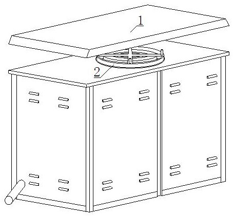
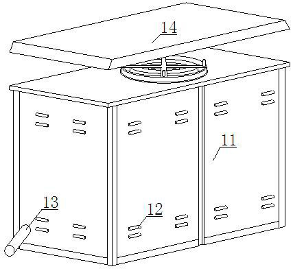
[0027] see Figure 1-3 , comprising a power cabinet 1 and a dehumidification device 2, the inside of the power cabinet 1 is equipped with a dehumidification device 2, the power cabinet 1 is provided with an organic casing 11, a deflector 12, a drainage pipe 13 and a top cover 14, and the side wall of the cabinet 11 is provided with There is a deflector 12, the casing 11 is provided with an inner shell 111 and an air vent 112, the side wall of the inner shell 111 is provided with an air vent 112, and the air vent 112 is arranged on the lower side of the air guide 12, through the inner shell 111 The side wall is provided with a vent 112, and the vent 112 is arranged on the lower side of the air guide 12, so that the circulation air path is in an S-shaped direction, which can effectively prevent water vapor from entering the power cabinet 1 in seasons or areas where the air is relatively humid. Inside, a drainage pipe 13 is installed on the other side wall of the casing 11 , and ...


PUM


Abstract

The invention discloses an electric power cabinet with a built-in dehumidification mechanism, which comprises an electric power cabinet and a dehumidification device, wherein the dehumidification device is installed in the electric power cabinet, a ventilation opening is formed in the side wall of an inner shell, the ventilation opening is formed in the lower side of a flow guide awning, a circulating air path is in an S-shaped trend, and water vapor is effectively prevented from entering the electric power cabinet; a first filter screen and a second filter screen are arranged at an air inlet,and the double filter screens can adsorb moisture in the air; an evaporator and a condenser are arranged in the electric power cabinet, the relative humidity is reduced, a good dehumidification effect is achieved, and potential power hazards are avoided; and a water outlet pipe is connected with a water inlet, and the water vapor generated by the evaporator flows into a water storage tank of a heating device to serve as reserve water of a heating assembly. The use is convenient, the heating assembly can preheat the evaporator and the water outlet pipe in cold air, condensation in the equipment is avoided, creepage accidents are avoided, the accident occurrence probability is reduced, and the safety of the electric power cabinet is improved.

Description

technical field [0001] The invention relates to the technical field of power configuration, in particular to a power cabinet with a built-in dehumidification mechanism. Background technique [0002] The electrical appliances in daily life are constantly increasing, and a lot of manual labor is replaced by electronic equipment. The stability of electric power needs to be guaranteed by qualified equipment. Among them, the new type of power cabinet improves the technology on the basis of traditional product features, such as the modular installation of internal parts. , You can choose to install a second-story door or a cradle, the overall form is beautiful and generous, forming a high-end switchboard, which is widely used in the electric power and electronic control industries. [0003] Nowadays, the power cabinets are located in areas with low temperature and high humidity, which is prone to circuit aging. At the same time, the internal humidity of the power cabinet is too hi...

Claims


Application Information

Patent Timeline
Patent Type & Authority Applications(China)
IPC IPC(8): H02B1/30H02B1/28H02B1/56
CPCH02B1/28H02B1/30H02B1/565
Inventor 刘一锋
Owner 苏州八度阳光智能科技有限公司
Learn More