Polyurethane sprayed polyethylene wound heat preservation pipe manufacturing equipment and process

A polyethylene and polyurethane technology, which is applied in the field of polyurethane sprayed polyethylene winding insulation pipe manufacturing equipment and manufacturing technology, can solve the problems of unfavorable use, reduced efficiency, high maintenance cost, etc., and achieve the effect of improving efficiency

Pending Publication Date: 2020-09-15
辽宁鸿鑫节能科技有限公司
View PDF0 Cites 3 Cited by
  • Summary
  • Abstract
  • Description
  • Claims
  • Application Information

AI Technical Summary

Problems solved by technology

[0003] At present, most of the polyurethane sprayed polyethylene winding insulation pipes on the market have relatively simple equipment design, and there is no structure for better clamping the pipe body and driving its rotation, which leads to the need for polyurethane spraying structures and polyethylene The spraying structure is effectively rotated to achieve the effect of spraying. This setting greatly increases the complexity of the polyurethane spraying structure and polyethylene spraying structure, which is not conducive to use, and the later maintenance costs are high. Some polyurethane spraying polyethylene winding insulation pipes The manufactured equipment lacks multiple feeding structures, so that it can only perform a single loading and unloading process, which greatly reduces the production efficiency. Therefore, in view of the above problems, a polyurethane sprayed polyethylene winding insulation pipe manufacturing equipment and manufacturing process

Method used


Image

  • Polyurethane sprayed polyethylene wound heat preservation pipe manufacturing equipment and process
  • Polyurethane sprayed polyethylene wound heat preservation pipe manufacturing equipment and process
  • Polyurethane sprayed polyethylene wound heat preservation pipe manufacturing equipment and process

Examples


Embodiment 1

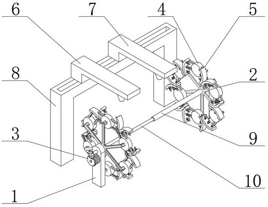
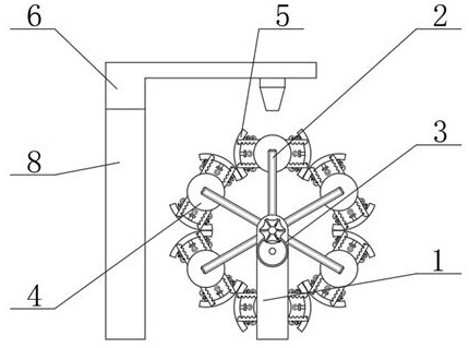
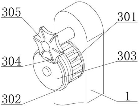
[0025] Example 1: See Figure 1-5 , the present invention provides a technical solution:

[0026] A polyurethane sprayed polyethylene winding insulation pipe manufacturing equipment, including a support column 1, a support frame 2, an intermittent rotation device 3, a clamping drive device 4, a limit rotation device 5, a polyurethane sprayed structure 6 and a polyethylene sprayed structure 7, the support The top of the inner surface of the column 1 is rotatably connected with a support frame 2, and the outside of the other end of the support frame 2 is fixedly installed with a clamping drive device 4, and both sides of the clamping drive device 4 are fixedly installed with a limit rotation device 5, which is located on one side. The other side of the support column 1 is equipped with an intermittent rotation device 3, and the rear side of the support column 1 is equipped with a fixed frame 8, and the top of the fixed frame 8 is slidably installed with a polyurethane spraying s...

Embodiment 2

[0029] Example 2: See Figure 1-5 , the present invention provides a technical solution:

[0030] A polyurethane sprayed polyethylene winding insulation pipe manufacturing equipment, including a support column 1, a support frame 2, an intermittent rotation device 3, a clamping drive device 4, a limit rotation device 5, a polyurethane sprayed structure 6 and a polyethylene sprayed structure 7, the support The top of the inner surface of the column 1 is rotatably connected with a support frame 2, and the outside of the other end of the support frame 2 is fixedly installed with a clamping drive device 4, and both sides of the clamping drive device 4 are fixedly installed with a limit rotation device 5, which is located on one side. The other side of the support column 1 is equipped with an intermittent rotation device 3, and the rear side of the support column 1 is equipped with a fixed frame 8, and the top of the fixed frame 8 is slidably installed with a polyurethane spraying s...


PUM


Abstract

The invention relates to the technical field of heat preservation pipe manufacturing, in particular to a polyurethane sprayed polyethylene wound heat preservation pipe manufacturing equipment and process. The polyurethane sprayed polyethylene wound heat preservation pipe manufacturing equipment includes supporting columns, supporting frames, intermittent rotation devices, clamping drive devices, limit rotation devices, a polyurethane spraying structure and a polyethylene spraying structure, the tops of the inner side surfaces of the supporting columns are rotatably connected with the supporting frames, the clamping drive devices are fixedly arranged on the outer sides of the other ends of the supporting frames, the limited rotation devices are fixedly arranged on two sides of the clampingdrive devices, the intermittent rotation devices are arranged on the other sides of the supporting columns on one side, a fixed frame is arranged on the rear sides of the supporting columns, and the polyurethane spraying structure and the polyethylene spraying structure are slidably arranged at the top end of the fixed frame. According to the polyurethane sprayed polyethylene wound heat preservation pipe manufacturing equipment and process, a heat preservation pipe to be processed can be better and effectively clamped and fixed by arranging the clamping drive devices and the limit rotation devices and can be better driven to rotate, so that a coating can be better sprayed on the surface of the heat preservation pipe.

Description

technical field [0001] The invention relates to the technical field of heat preservation pipe manufacturing, in particular to a polyurethane sprayed polyethylene winding heat preservation pipe manufacturing equipment and manufacturing process. Background technique [0002] Insulation pipes are an important factor affecting energy conservation. The development and application of insulation pipes have attracted more and more attention from all over the world. After the 1970s, foreign countries generally paid attention to the production and application of insulation pipes, and strived to greatly reduce energy consumption. In order to reduce environmental pollution and greenhouse effect, thermal insulation pipe is the abbreviation of thermal insulation pipe, and thermal insulation pipe is used for the transportation of liquid, gas and other media. Insulation engineering heat preservation, polyurethane insulation pipe is divided into three layers from inside to outside: the first...

Claims


Application Information

Patent Timeline
Patent Type & Authority Applications(China)
IPC IPC(8): B29D23/00
CPCB29D23/001
Inventor 宁江涛赵英王庆成钱有国林琛刘丽娟孙平
Owner 辽宁鸿鑫节能科技有限公司
Why Eureka
Try Eureka