Double-spindle movable gantry ultra-long stroke machining center used for drilling and milling steel rail joint part

A machining center and double-spindle technology, applied in metal processing equipment, metal processing machinery parts, manufacturing tools, etc., can solve problems such as low efficiency, low degree of automation of rails, and inability to clamp at one time, achieving high efficiency and difficult equipment operation The effect of lowering and fast moving speed

Pending Publication Date: 2020-09-15
沈阳大道机床有限公司
View PDF0 Cites 3 Cited by
  • Summary
  • Abstract
  • Description
  • Claims
  • Application Information

AI Technical Summary

Problems solved by technology

[0003] The purpose of the present invention is to solve the problems of low automation and low efficiency in processing rails by existing numerical control equipment, and it is impossible to complete them in one clamping, and specially provides a dual-spindle dynamic gantry super long-stroke machining center for drilling and milling of rail junctions.

Method used


Image

  • Double-spindle movable gantry ultra-long stroke machining center used for drilling and milling steel rail joint part
  • Double-spindle movable gantry ultra-long stroke machining center used for drilling and milling steel rail joint part
  • Double-spindle movable gantry ultra-long stroke machining center used for drilling and milling steel rail joint part

Examples


Embodiment 1

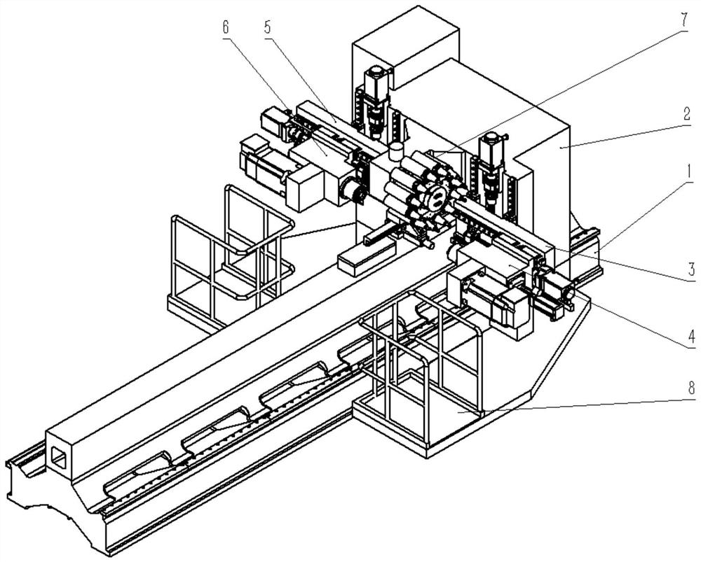
[0030] The invention provides a dual-spindle dynamic gantry super-long-stroke machining center for drilling and milling of rail junctions, which is characterized in that: the dual-spindle dynamic gantry super-long-stroke machining center for drilling and milling of rail junctions includes a bed 1. Gantry frame 2, main processing side slide seat 3, main processing side spindle box 4, auxiliary processing side slide seat 5, auxiliary processing side spindle box 6, fan-shaped servo tool magazine 7, operation table 8;

[0031] Among them: the bed 1 is provided with a gantry frame 2, the main processing side slide seat 3 and the main processing side spindle box 4 are arranged on one side of the bed 1, and the secondary processing side slide seat 5 and the secondary processing side spindle box 6 are arranged on the bed. On the other side of the body 1, the fan-shaped servo tool magazine 7 is set between the main processing side spindle box 4 and the sub-processing side spindle box 6,...

Embodiment 2

[0044] The invention provides a dual-spindle dynamic gantry super-long-stroke machining center for drilling and milling of rail junctions, which is characterized in that: the dual-spindle dynamic gantry super-long-stroke machining center for drilling and milling of rail junctions includes a bed 1. Gantry frame 2, main processing side slide seat 3, main processing side spindle box 4, auxiliary processing side slide seat 5, auxiliary processing side spindle box 6, fan-shaped servo tool magazine 7, operation table 8;

[0045] Among them: the bed 1 is provided with a gantry frame 2, the main processing side slide seat 3 and the main processing side spindle box 4 are arranged on one side of the bed 1, and the secondary processing side slide seat 5 and the secondary processing side spindle box 6 are arranged on the bed. On the other side of the body 1, the fan-shaped servo tool magazine 7 is set between the main processing side spindle box 4 and the sub-processing side spindle box 6,...

Embodiment 3

[0058] The invention provides a dual-spindle dynamic gantry super-long-stroke machining center for drilling and milling of rail junctions, which is characterized in that: the dual-spindle dynamic gantry super-long-stroke machining center for drilling and milling of rail junctions includes a bed 1. Gantry frame 2, main processing side slide seat 3, main processing side spindle box 4, auxiliary processing side slide seat 5, auxiliary processing side spindle box 6, fan-shaped servo tool magazine 7, operation table 8;

[0059] Among them: the bed 1 is provided with a gantry frame 2, the main processing side slide seat 3 and the main processing side spindle box 4 are arranged on one side of the bed 1, and the secondary processing side slide seat 5 and the secondary processing side spindle box 6 are arranged on the bed. On the other side of the body 1, the fan-shaped servo tool magazine 7 is set between the main processing side spindle box 4 and the sub-processing side spindle box 6,...


PUM


Abstract

The invention provides a double-spindle movable gantry ultra-long stroke machining center used for drilling and milling a steel rail joint part. A gantry frame is arranged on a machine body; a main machining side slide seat and a main machining side spindle box are placed above one side of the machine body; a sub machining side slide seat and a sub machining side spindle box are placed above the other side of the machine body; a fan-shaped servo tool magazine is arranged between the main machining side spindle box and the sub machining side spindle box; an operation platform is arranged on thetwo sides of the machine body; the length of the single machine body is 6m and adopts a structural form of a spliced machine body; the machine body length of a single machine is 30m and the machine body of the single machine can extends for a longest distance of 54m; a gantry is single side drive; and a main guide machining side adopts a linear guide rail with pre-tensioning. The double-spindle movable gantry ultra-long stroke machining center used for drilling and milling the steel rail joint part has the advantages that the blank of special steel rail machining equipment is filled, 27m longsteel rail can be machined at one time, the machine can extend for a longest distance of 54m, and the equipment operation difficulty is reduced. The problem that the repeated positioning accuracy islow due to large parallelism error between two linear guide rails of a traditional structure in a long stroke is solved; and the machining efficiency is enhanced.

Description

technical field [0001] The present invention relates to the layout structure field of double-side hanging box opposite dual-spindle dynamic gantry ultra-long stroke machining center used for drilling and milling of rail joints, and in particular relates to a double-spindle dynamic gantry super-long for drilling and milling of rail joints Stroke machining center. Background technique [0002] The rails used in high-speed railways and intercity rails are all segmented, and are reassembled at the construction site, so the rails need to be pre-drilled, milled, chamfered, etc. The current equipment used is non-professional processing equipment. The processing efficiency and degree of automation are low. Contents of the invention [0003] The object of the present invention is to solve the problems of low automation and low efficiency of processing rails by existing numerical control equipment, and it is impossible to complete the processing in one clamping, and specially provi...

Claims


Application Information

Patent Timeline
Patent Type & Authority Applications(China)
IPC IPC(8): B23P23/02B23Q1/01B23Q1/70B23Q3/154B23Q3/157
CPCB23P23/02B23Q1/01B23Q1/012B23Q1/017B23Q1/70B23Q3/1543B23Q3/157
Inventor 董威常亮张东华陈伟王旭金彦蛟
Owner 沈阳大道机床有限公司
Why Eureka
Try Eureka