
Two-dimensional maxillary molar moving device

A technology of moving devices and mounting holes, which is applied in dentistry, implantology, orthodontics, etc., can solve the problems of small diameter of micro-implantation nails, bending of nails, and increased pain of patients, so as to reduce the risk of failure and reduce the risk of buccal The effect of tilting and improving clinical efficiency

Pending Publication Date: 2020-09-15
SHANGHAI XUHUI DISTRICT DENTAL CENT
View PDF0 Cites 4 Cited by
  • Summary
  • Abstract
  • Description
  • Claims
  • Application Information

AI Technical Summary

Problems solved by technology

The current bony rapid expander on the market directly connects the micro-implant nails and the expander. For cases with obvious dental arch stenosis, there are problems in choosing to use this type of rapid expander: (1) The palatal vault is too narrow, The selected expander can only be as narrow as possible, but the amount of expansion of the narrow expander is limited, and it cannot meet the clinical needs at one time, that is, it is necessary to replace the wider expander when the expander reaches a certain level , replacement of the appliance requires re-implantation of micro-screws, on the one hand, it increases the pain of the patient, and on the other hand, it increases the risk of subsequent micro-screw implantation failure, and the clinical cost increases
(2) There is a large distance between the arch expander and the top of the palatal vault, and it is necessary to use special micro-implantation screws long enough to provide sufficient retention in clinical practice. There is a large distance between the screw threads, and the diameter of the micro-implantation screw is small, and there is a risk of the nail bending, breaking or falling off during the force application process

Method used


Image

  • Two-dimensional maxillary molar moving device
  • Two-dimensional maxillary molar moving device
  • Two-dimensional maxillary molar moving device

Examples


Embodiment 1

[0025] combine Figure 1-3 The structure of the present invention is described.

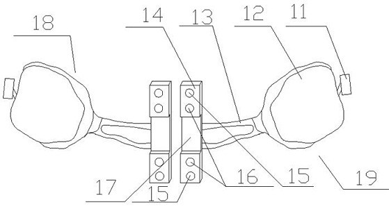
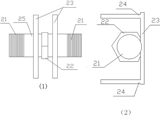
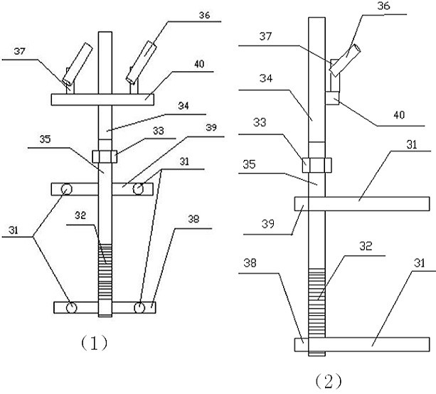
[0026] The two-dimensional maxillary molar moving device includes left and right retaining parts 19, 18 and force-reinforcing parts. The metal crown 12 of the first molar and the retaining plate 14 with a transverse groove 17 in the middle, the metal crown 12 and the retaining plate 14 are arranged on the same side of the palatal crevice and connected by a steel wire 13, the buccal side of the metal crown 12 corresponds to The maxillary zygomatic alveolar ridge is connected with a micro-implantation nail sleeve 11, and the two ends of the sagittal direction of the retention plate 14 are respectively provided with mounting holes 15 for force-reinforcing components. The diameter of the force component mounting hole 15 is 1.51mm, and the depth is 2mm.

[0027] The retaining plate 14 of each retaining part fits the upper jaw to ensure that the micro-implantation screw can be implanted into the bone...

Embodiment 2

[0033] Embodiment 2 Application of the present invention

[0034] The two-dimensional maxillary molar moving device in Example 1 is used to correct the maxillary posterior occlusal occlusion, the maxillary width is seriously insufficient and the degree of crowding is not large. The following is the specific installation method of the present invention as follows:

[0035] (1) One micro-screw implantation is placed on the bilateral maxillary zygomatic alveolar ridges (the anatomical position is generally on the buccal side of the maxillary first molar).

[0036] (2) The maxillary model was taken, superhard gypsum was cast, and the left and right maxillary first molar cast crowns were made respectively, and a micro-screw sleeve was extended on the buccal side. The casting crown was placed on the first molar, and the micro implant sleeve was placed on the implant screw at the zygomatic alveolar ridge.

[0037] (3) The retention plate was stably connected with the auxiliary posit...


PUM


Abstract

The invention provides a two-dimensional maxillary molar moving device, and relates to the field of orthodontic instruments. The two-dimensional maxillary molar moving device comprises left and rightretention parts and a stressing part; the left and right retention parts are respectively arranged at the left and right sides of the palatal suture; the stressing part is connected with the left andright retention parts; each retention part comprises a metal crown covering the first molar, and a retention plate with a transverse groove in the middle; the metal crown and the retention plate are arranged at the same side of the palatal suture, and connected through a steel wire; the buccal side of the metal crown is connected to an implant nail sleeve corresponding to the maxillary zygomatic alveolar ridge; and two sagittal ends of the retention plate are respectively provided with stressing part installation holes. The retention parts in the invention can be appressed to the palatal mucous membrane to the most extent; a micro implant nail can be implanted in bone to the most extent; the failure risk in the stressing process of the micro implant nail can be reduced; and furthermore, ina correction process, the transverse enough width change of the maxillary can be realized without disassembling the micro implant nail.

Description

technical field [0001] The invention relates to the field of orthodontic instruments, in particular to a clinical two-dimensional maxillary molar moving device. [0002] technical background [0003] Protruding upper dentition with narrow upper dental arch is relatively common in clinical practice. For narrow upper dental arch, the current expansion methods include: fast spiral expander, knight bow and four-eye coil spring. For the rapid expansion of the adult arch, it is often necessary to expand the arch with micro-implant screws on both sides of the palatal suture, so as to avoid the buccal inclination of the upper posterior teeth caused by the direct use of the rapid expansion device. The current bony rapid expander on the market directly connects the micro-implant nails and the expander. For cases with obvious dental arch stenosis, there are problems in choosing to use this type of rapid expander: (1) The palatal vault is too narrow, The selected expander can only be as...

Claims


Application Information

Patent Timeline
IPC IPC(8): A61C7/00A61C8/00A61C7/08
CPCA61C7/00A61C7/08A61C8/0096
Inventor 钱文昊马晓晴
Owner SHANGHAI XUHUI DISTRICT DENTAL CENT
Learn More