
Movable numerical control drilling machine capable of preventing iron filings from splashing around

A CNC drilling machine, four-way technology, applied to boring machine/drilling machine parts, drilling/drilling equipment, large fixed members, etc., can solve the problems of inconvenient movement, iron filings splashing, etc., to improve safety and prevent iron filings from moving around Effects of splashing and preventing workers from being injured

Inactive Publication Date: 2020-09-11
泰州天融科技有限公司
View PDF7 Cites 12 Cited by
  • Summary
  • Abstract
  • Description
  • Claims
  • Application Information

AI Technical Summary

Problems solved by technology

[0003] During the working process of the existing CNC drilling machine, iron filings splash around and it is inconvenient to move

Method used


Image

  • Movable numerical control drilling machine capable of preventing iron filings from splashing around
  • Movable numerical control drilling machine capable of preventing iron filings from splashing around
  • Movable numerical control drilling machine capable of preventing iron filings from splashing around

Examples


Embodiment 1

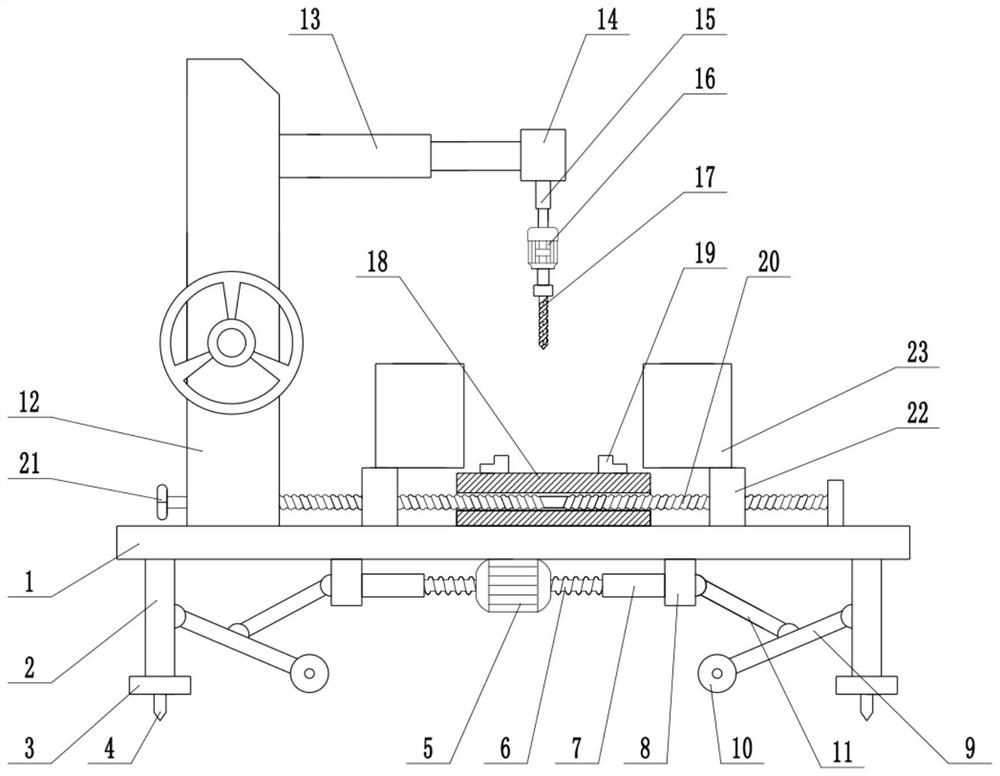
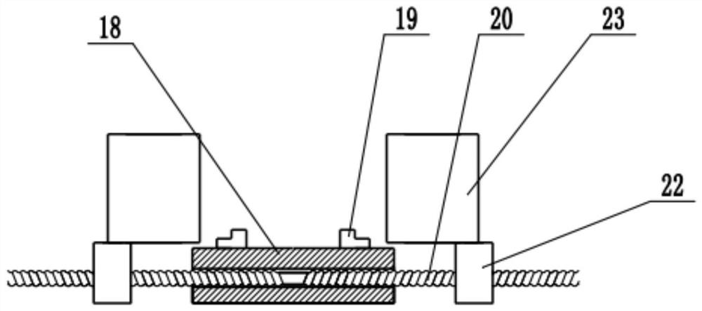
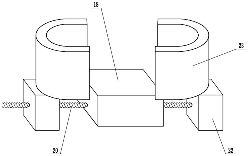
[0022] see Figure 1-3 , in an embodiment of the present invention, a movable CNC drilling machine for preventing iron filings from splashing around, including a base 1, a support plate 2, a frame 12, a first telescopic mechanism 13, a mounting block 14, a second telescopic mechanism 15, a drill Hole motor 16 and drill bit 17, the bottom of base 1 is fixedly connected with support plate 2, and the lower end of support plate 2 is fixedly connected with support foot 3, and the lower surface of support foot 3 is equipped with fixed pile 4, and fixed pile 4 is embedded in the ground, can improve The stability of this device, the upper surface of base 1 is fixedly connected with frame 12, and the sidewall of frame 12 is equipped with first telescopic mechanism 13, and the first telescopic mechanism 13 is electrohydraulic telescopic cylinder, and the first telescopic mechanism 13 The extension end is fixedly connected with a mounting block 14, which controls the expansion and contra...

Embodiment 2

[0024] On the basis of Embodiment 1, a moving mechanism is installed on the bottom of the base 1, and the moving mechanism includes a biaxial motor 5, an adjusting screw 6, a sleeve 7, a moving block 8, a movable rod 9, a universal wheel 10 and a connecting rod 11. A biaxial motor 5 is fixedly connected to the bottom of the base 1. The biaxial motor 5 is a positive and negative motor. A sleeve 7 is sleeved, and the end of the sleeve 7 is fixedly connected with a moving block 8. The upper surface of the moving block 8 is slidingly connected with the bottom of the base 1, and controls the forward and reverse rotation of the biaxial motor 5, which can drive and adjust the screw rod 6 Forward and reverse, thereby driving the moving block 8 to move left and right, the side wall of the support plate 2 is hinged with a movable rod 9, and the lower end of the movable rod 9 is equipped with a universal wheel 10, and the side wall of the moving block 8 is hinged with a connecting rod 11....


PUM


Abstract

The invention relates to the field of machining equipment, in particular to a movable numerical control drilling machine capable of preventing iron filings from splashing around. The movable numericalcontrol drilling machine capable of preventing the iron filings from splashing around comprises a base, a supporting plate, a machine frame, a first telescopic mechanism, a mounting block, a second telescopic mechanism, a drilling motor and a drilling bit, the bottom of the base is fixedly connected with the supporting plate, the upper surface of the base is fixedly connected with the machine frame, the first telescopic mechanism is arranged on the side wall of the machine frame, and the extension end of the first telescopic mechanism is fixedly connected with the mounting block; the lower surface of the mounting block is fixedly connected with the second telescopic mechanism, a drilling platform is installed on the upper surface of the base, a two-way screw rod penetrates through the side wall of the drilling platform, and sliding blocks are symmetrically arranged on the left side and the right side of the drilling platform; and the upper surfaces of the sliding blocks are fixedly connected with baffles, and a moving mechanism is arranged at the bottom of the base. A part to be machined is placed on the drilling platform. The baffles are used for covering the part to be machinedto prevent the iron filings from splashing around during the drilling operation, workers are prevented from being injured, and safety is greatly improved.

Description

technical field [0001] The invention relates to the field of mechanical processing equipment, in particular to a movable numerical control drilling machine which prevents iron filings from splashing around. Background technique [0002] Drilling machine refers to a machine tool that mainly uses a drill bit to process holes in a workpiece. Generally, the rotation of the drill bit is the main movement, and the axial movement of the drill bit is the feed movement. The drilling machine has a simple structure and relatively low machining accuracy. It can drill through holes and blind holes, replace special tools, expand, countersink, ream or tap. During the machining process, the workpiece does not move, let the tool move, align the center of the tool with the center of the hole, and make the tool rotate (main movement). The characteristic of the drilling machine is that the workpiece is fixed and the tool rotates. [0003] During the working process of the existing numerical ...

Claims


Application Information

Patent Timeline
Patent Type & Authority Applications(China)
IPC IPC(8): B23Q11/08B23B47/00B23Q1/00
CPCB23B47/00B23Q1/00B23Q11/08
Inventor 张蕾
Owner 泰州天融科技有限公司
Learn More