
Oil field orderly power utilization system with topological structure and orderly power utilization distribution method thereof

A topology and power system technology, applied in the direction of power network operating system integration, information technology support system, electrical components, etc., can solve the problem of inability to maximize the overall benefit of the oil field, lack of evaluation principles and evaluation methods, and inability to grasp the implementation in real time Situation and other issues

Active Publication Date: 2020-09-08
CHINA PETROLEUM & CHEM CORP +1
View PDF6 Cites 0 Cited by
  • Summary
  • Abstract
  • Description
  • Claims
  • Application Information

AI Technical Summary

Problems solved by technology

[0005] (1) At present, only the proportion of production electricity consumption of production units is considered as the basis for the decomposition of power reduction tasks, and the value of electricity consumption of each development unit is not fully considered, which is not conducive to the optimal allocation of electricity loads;
[0006] (2) It mainly relies on experience to manually formulate orderly power consumption plans, lacks scientific decision-making theoretical support, and cannot maximize the overall benefit of the oilfield;
[0007] (3) The evaluation after the implementation of orderly electricity use lacks reasonable evaluation principles and evaluation methods, and fails to fully reflect the negative impact of orderly electricity use after implementation;
[0008] (4) There is a lack of effective and orderly power consumption throughout the process, and it is impossible to grasp the implementation situation in real time

Method used


Image

  • Oil field orderly power utilization system with topological structure and orderly power utilization distribution method thereof
  • Oil field orderly power utilization system with topological structure and orderly power utilization distribution method thereof
  • Oil field orderly power utilization system with topological structure and orderly power utilization distribution method thereof

Examples


Embodiment Construction

[0069] In order to make the purpose, technical solution and advantages of the present invention clearer, the technical solution of the present invention will be described in detail below. Apparently, the described embodiments are only some of the embodiments of the present invention, but not all of them. Based on the embodiments of the present invention, all other implementations obtained by persons of ordinary skill in the art without making creative efforts fall within the protection scope of the present invention.

[0070] A topology-structured oilfield orderly power consumption system and its method for orderly power consumption distribution

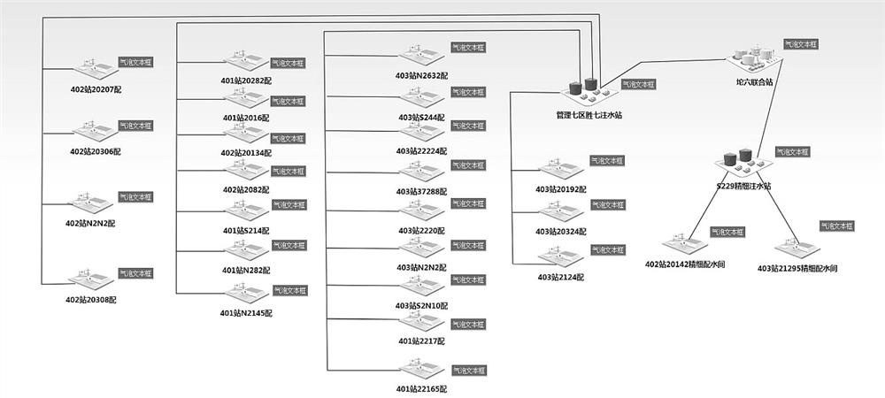
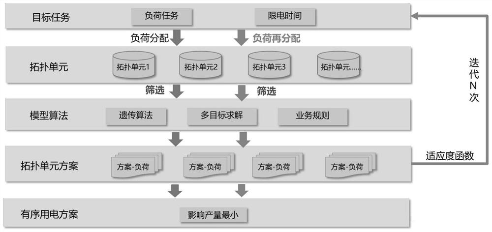
[0071] like figure 1 As shown, the system includes a business rule module, an oilfield topology and a calculation model. The business rule module includes: pump shutdown rules, well shutdown rules, and other business rules, among which:

[0072] Pump stop rules: give priority to stop the water injection pump with high power and low...


PUM


Abstract

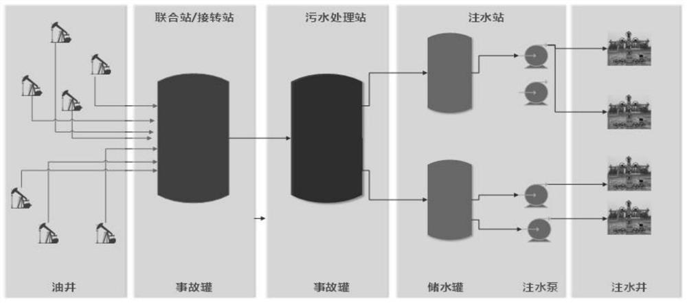
The invention discloses an oil field orderly power utilization system with a topological structure and an orderly power utilization distribution method thereof. The system comprises a business rule module, an oil field topological structure and a calculation model, the oil field topological structure is composed of topological units, each topological unit comprises an oil well, a combination station, an oil well, a gathering and transportation station library, a water injection station and a water well, the combination stations, the transfer stations and the produced water treatment stations serve as hubs, the oil wells, the water injection pumps and the water injection wells are associated to sewage storage equipment according to the actual physical relation, and therefore a relatively independent production system is formed to form the topological units. Emergency storage capacities in the system are communicated with each other; the oil well produced liquid and water injected by thewater injection pump only influence the emergency reservoir capacity change of the system; a relatively stable water transfer relationship with other production systems can be kept; and the accidenttank and the water storage tank are used as sewage storage equipment in a unified manner, and the sewage storage equipment is used as an initial node of the topology unit.

Description

technical field [0001] The invention relates to the field of orderly power utilization in oilfields, in particular to a system for orderly power utilization in oilfields with a topological structure and a method for distributing orderly power utilization in oilfields. Background technique [0002] In recent years, with the continuous increase of local industrial electricity consumption and residential electricity consumption, under the high temperature weather in summer, there will often be a shortage of electricity supply. It is necessary for the oil field to take a series of measures such as shifting peaks, avoiding peaks, and limiting electricity to ensure that residents Electricity for life. Especially in an emergency state, the power supply company quickly reduces the load by directly switching on the substation. This disorderly switching and power reduction method has brought some unnecessary losses to the oilfield production. In the case of orderly power consumption,...

Claims


Application Information

Patent Timeline
Patent Type & Authority Applications(China)
IPC IPC(8): G06Q10/04G06Q10/06G06Q50/06E21B43/20E21B49/08H02J3/00H02J3/14
CPCG06Q10/04G06Q10/06315G06Q10/0639G06Q50/06E21B43/20E21B49/08H02J3/007H02J3/14H02J2310/56Y04S20/222Y02B70/3225
Inventor 袁晓鹏刘广友周涛李颖张元法巴伟何斌马鹏举孙柏东金文磊张鹏程庄涛谷雨
Owner CHINA PETROLEUM & CHEM CORP
Learn More