
Methods for determining boundaries and configurations of interplanetary magnetic flux rope

A magnetic flux, planetary technology, applied in the direction of measuring magnetic variables, measuring devices, complex mathematical operations, etc., can solve problems such as complex methods

Active Publication Date: 2020-09-08
LUOYANG NORMAL UNIV
View PDF2 Cites 0 Cited by
  • Summary
  • Abstract
  • Description
  • Claims
  • Application Information

AI Technical Summary

Problems solved by technology

The current method is also more complex

Method used


Image

  • Methods for determining boundaries and configurations of interplanetary magnetic flux rope
  • Methods for determining boundaries and configurations of interplanetary magnetic flux rope
  • Methods for determining boundaries and configurations of interplanetary magnetic flux rope

Examples


Embodiment 1

[0062] Example 1: The magnetic cloud event on October 18-20, 1995.

[0063] On October 18-20, 1995, the magnetic cloud attracted much attention as a typical event. Figure 5 The magnetic field and plasma parameters of the solar wind detected by the Wind satellite on October 18-20, 1995 are given. Figure 5 From top to bottom, the x, y, z components (Bx, By, Bz) of the magnetic field in the GSE coordinate system, the total magnetic field strength (Bt), the velocity of the solar wind along the sun-earth direction (Vx), and the thermal velocity of protons ( Vth), proton density (N) and plasma β value. At 10:56UT on the 18th, the satellite first detected the leading shock wave of this event, from Figure 5 It can be seen that 18:58 UT on the 18th is a very obvious discontinuity, and this discontinuity is confirmed to be TD, and here the plasma β value, proton density, and thermal velocity all drop suddenly; the magnetic field component and the total magnetic field intensity are ...

Embodiment 2

[0068] Example 2: March 19-22, 2001 magnetic cloud event.

[0069] Figure 7 Given the variation curves of the solar wind's magnetic field and plasma parameters from March 19 to 22, 2001, it can be known that this event is still expanding from the slowly decreasing velocity profile. The vertical dotted lines in the figure indicate that FB1 at 17:00UT on March 19 and RB1 at 22:00UT on March 21 are the front and rear boundaries of the magnetic cloud time given by Can and Richardson respectively. However, between 17:00-20:00 UT on the 19th, the plasma β value, proton density, and temperature of the solar wind were all high, so this section is likely to be the interaction between the magnetic cloud and the background medium to form a sheath or sheath at the front part of the layer, not part of the flux rope. In addition, there are many fluctuations in the plasma β value, proton density and total magnetic field strength in the front of the MC, without obvious decrease (or increas...


PUM


Abstract

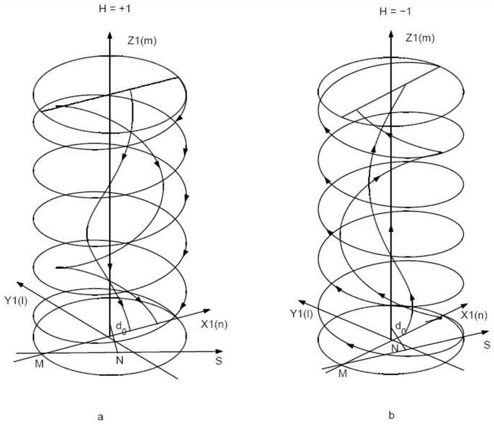
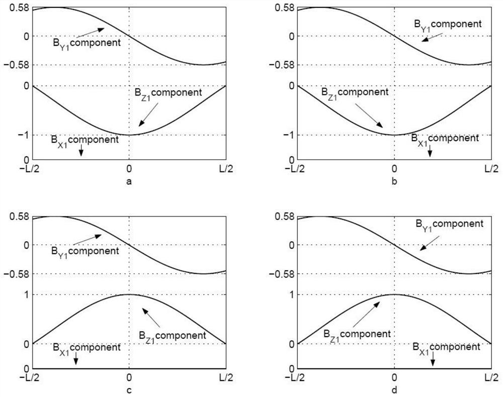
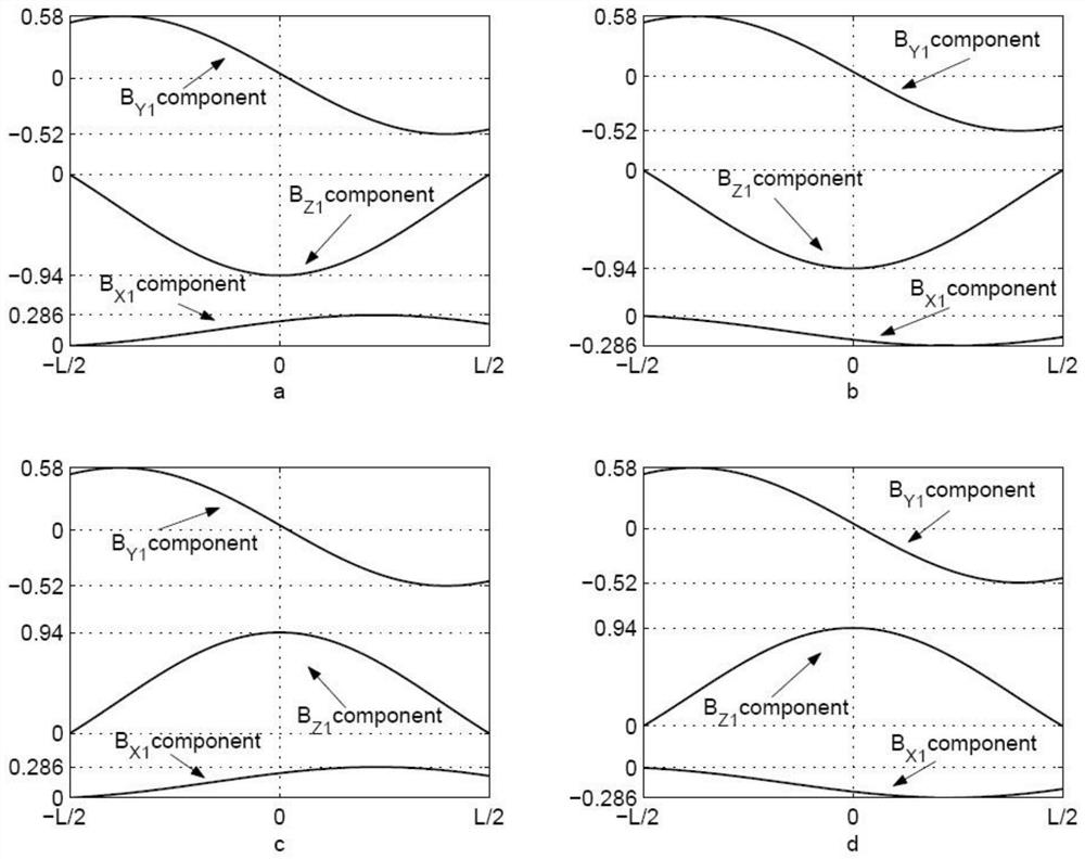
The invention relates to the technical field of magnetic flux ropes, in particular to a method for determining the boundary and configuration of an interplanetary magnetic flux rope. The method comprises the following steps: establishing a magnetic cloud natural coordinate system, and determining a magnetic field component expression of a flux rope in the magnetic cloud natural coordinate system;determining a point M which is firstly detected by a satellite in the magnetic cloud and a point N which is closest to a magnetic cloud axis on a satellite orbit; determining a linear equation passingthrough the two points through the coordinates of the M point and the N point; and according to the magnetic field component expression of the flux rope and the linear equation passing through the Mpoint and the N point, obtaining the expression of the magnetic field detected by the satellite passing through the magnetic cloud. The invention provides a novel and simple method for determining themagnetic cloud boundary and the magnetic field configuration. When the method is used for determining the magnetic cloud boundary, the defect that the boundary is not universally determined accordingto magnetic field and plasma characteristics in the prior art is overcome, and meanwhile uncertainty is reduced.

Description

technical field [0001] The invention relates to the technical field of magnetic flux ropes, in particular to a method for determining the boundary and configuration of interplanetary magnetic flux ropes. Background technique [0002] As a large-scale magnetic flux rope structure in the interplanetary space, the magnetic cloud occupies a very important position in the fields of solar physics and space physics. Researchers have also done a lot of research on it, but many problems have not been solved so far. The magnetic cloud Determination of boundaries is one of them. Because the study of magnetic cloud boundary is directly related to the study of many other important issues. For example, in the study of the interaction between the magnetic cloud and the background solar wind, the determination of the magnetic cloud boundary is one of the key issues; The cloud boundary is also of great significance to the study of the interaction between the magnetic cloud and the magnetos...

Claims


Application Information

Patent Timeline
Patent Type & Authority Applications(China)
IPC IPC(8): G06F17/11G01R33/10
CPCG06F17/11G01R33/10
Inventor 冯恒强赵岩
Owner LUOYANG NORMAL UNIV
Learn More