Locomotive unit brake fatigue test device and test method

A fatigue test and brake technology, which is applied in the testing of machines/structural components, measuring devices, testing of mechanical components, etc., can solve the problems of large manpower and material consumption, long test period, difficulty in achieving the expected test effect, etc., and achieve automation The effect of low degree and high test efficiency

Pending Publication Date: 2020-09-08
HUNAN LIANCHENG TRACK EQUIP CO LTD +1
View PDF0 Cites 0 Cited by
  • Summary
  • Abstract
  • Description
  • Claims
  • Application Information

AI Technical Summary

Problems solved by technology

[0003] For the unit brakes currently installed on power-concentrated trains, there is no fatigue test device with a high degree of automation and less manual intervention. A large amount of manpower and materials, and the test period is long, it is difficult to achieve the expected effect of the test

Method used


Image

  • Locomotive unit brake fatigue test device and test method
  • Locomotive unit brake fatigue test device and test method

Examples


Embodiment 1

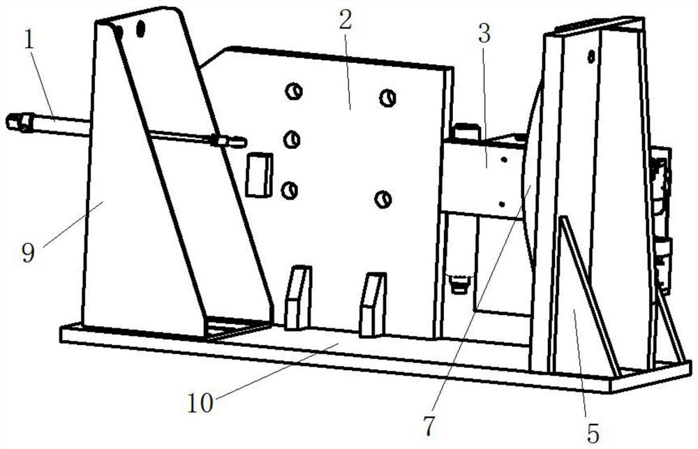
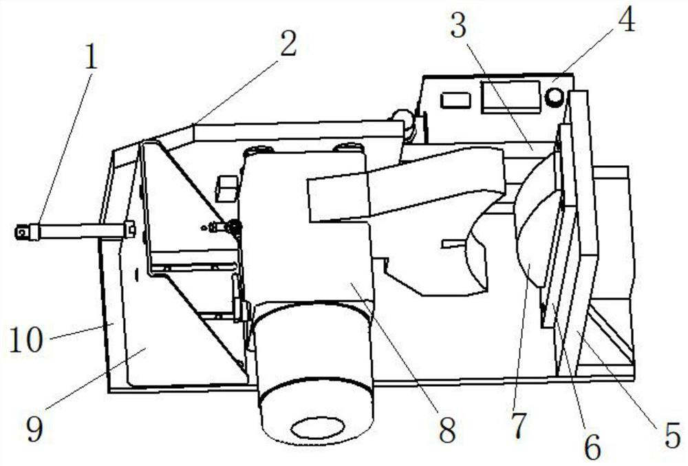
[0032] see Figure 1-2 , a locomotive unit brake fatigue test device, the fatigue test device includes a base, a wheel simulation unit and an action control module, the base is used to install the locomotive unit brake 8, the wheel simulation unit and the action control module are all set On the base, the wheel simulation unit cooperates with the locomotive unit brake 8 to realize wheel brake simulation, and the action control module is used to control the action of the locomotive unit brake 8 .

[0033] The action control module includes a control box 4 and a cylinder 1, the control box 4 is connected to the cylinder 1 and the locomotive unit brake 8, and the control box 4 is used to control the inflation or exhaust of the locomotive unit brake 8, thereby realizing wheel brake simulation. The cylinder 1 is retracted or stretched out to realize the locomotive unit brake 8 simulating the pulling of the wristband solution or the wristband solution homing.

[0034] The piston ro...


PUM


Abstract

The invention provides a locomotive unit brake fatigue test device. The fatigue test device comprises a base, a wheel simulation unit and an action control module, wherein the base is used for installing a locomotive unit brake, the wheel simulation unit and the action control module are both arranged on the base, the wheel simulation unit is matched with the locomotive unit brake to realize wheelbrake simulation, and the action control module is used for controlling the action of the locomotive unit brake. According to the locomotive unit brake fatigue test device, four actions of independently controlling the unit brake to inflate, deflate, pull the bracelet solution and return the bracelet solution can be realized through the action control module, and the requirement that the braceletsolution needs to be independently tested in a type test is met. The invention further provides a test method adopting the fatigue test device, the test method is simple to operate and low in manualintervention degree, and the labor intensity of personnel is reduced.

Description

technical field [0001] The invention relates to the technical field of fatigue testing of locomotive components, in particular to a fatigue testing device and testing method for a locomotive unit brake. Background technique [0002] Some components on a locomotive require fatigue testing, such as locomotive unit brakes. [0003] For the unit brakes currently installed on power-concentrated trains, there is no fatigue test device with a high degree of automation and less manual intervention. A large amount of manpower and materials are required, and the test cycle is long, so it is difficult to achieve the expected effect of the test. [0004] In summary, there is an urgent need for a locomotive unit brake fatigue test device and test method to solve the problems in the prior art. Contents of the invention [0005] The object of the present invention is to provide a kind of locomotive unit brake fatigue test device, and specific technical scheme is as follows: [0006] A...

Claims


Application Information

Patent Timeline
Patent Type & Authority Applications(China)
IPC IPC(8): G01M13/00
CPCG01M13/00
Inventor 周真贾仕贤龙骏彭龙刘金良
Owner HUNAN LIANCHENG TRACK EQUIP CO LTD
Why Eureka
Try Eureka