Diversion non-woven composite material synthesis device

A technology of composite materials and synthetic devices, applied in the field of composite diversion nets, can solve problems such as manual separation, achieve the effects of improving product quality, ensuring stable and continuous work, and improving the pressing effect

Inactive Publication Date: 2020-09-08
潘利斌
View PDF0 Cites 1 Cited by
  • Summary
  • Abstract
  • Description
  • Claims
  • Application Information

AI Technical Summary

Problems solved by technology

[0005] The purpose of the present invention is to address the deficiencies of the prior art, by setting the first gluing mechanism to infiltrate the upper surface of the diversion net after gluing to the squeegee of the lower surface of the diversion net through the grid of the diversion net Remove, and timely repair the scraped glue to the lower surface of the porous isolation film, on the one hand, it is conducive to timely glue repair work, to achieve effective bonding in later pressing; Scrape off in time, and then pre-scrape off most of the useless glue, which is beneficial to the composite flow guide net and will not cause mutual adhesion during winding, thus solving the problem of composite work between the flow guide net and the porous isolation film. The water-based glue on the rubber roller will flow out from the gap of the diversion net to the non-composite surface of the diversion net, which may cause the non-composite surface of the diversion net to stick to the contacting porous isolation film during winding One, so the technical problem that needs to be separated manually in later use

Method used


Image

  • Diversion non-woven composite material synthesis device
  • Diversion non-woven composite material synthesis device
  • Diversion non-woven composite material synthesis device

Examples


Embodiment 1

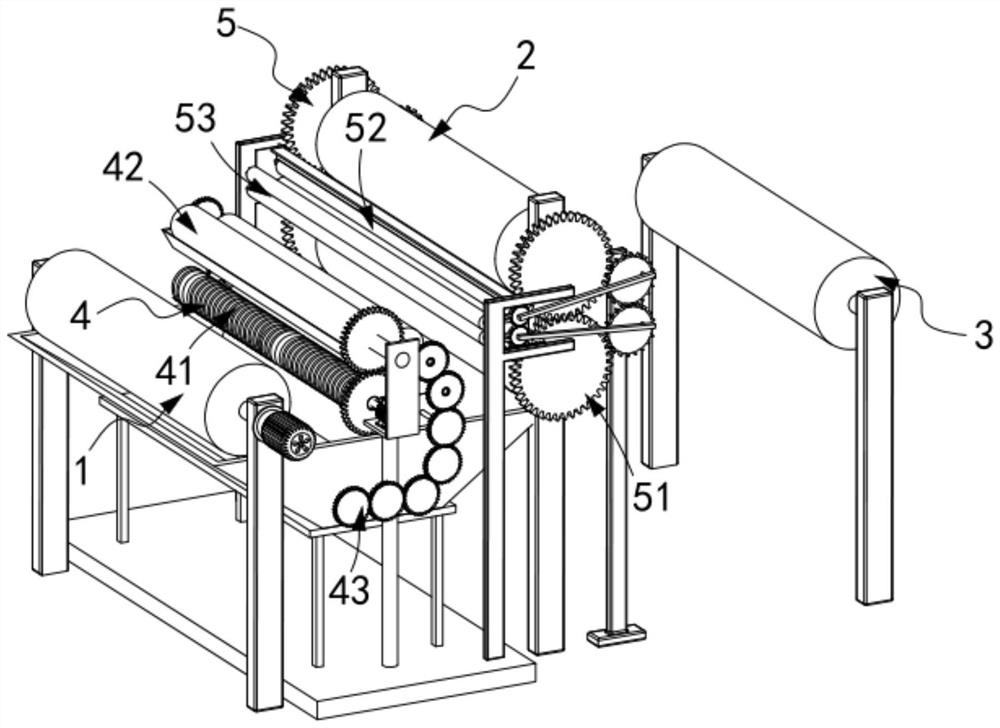
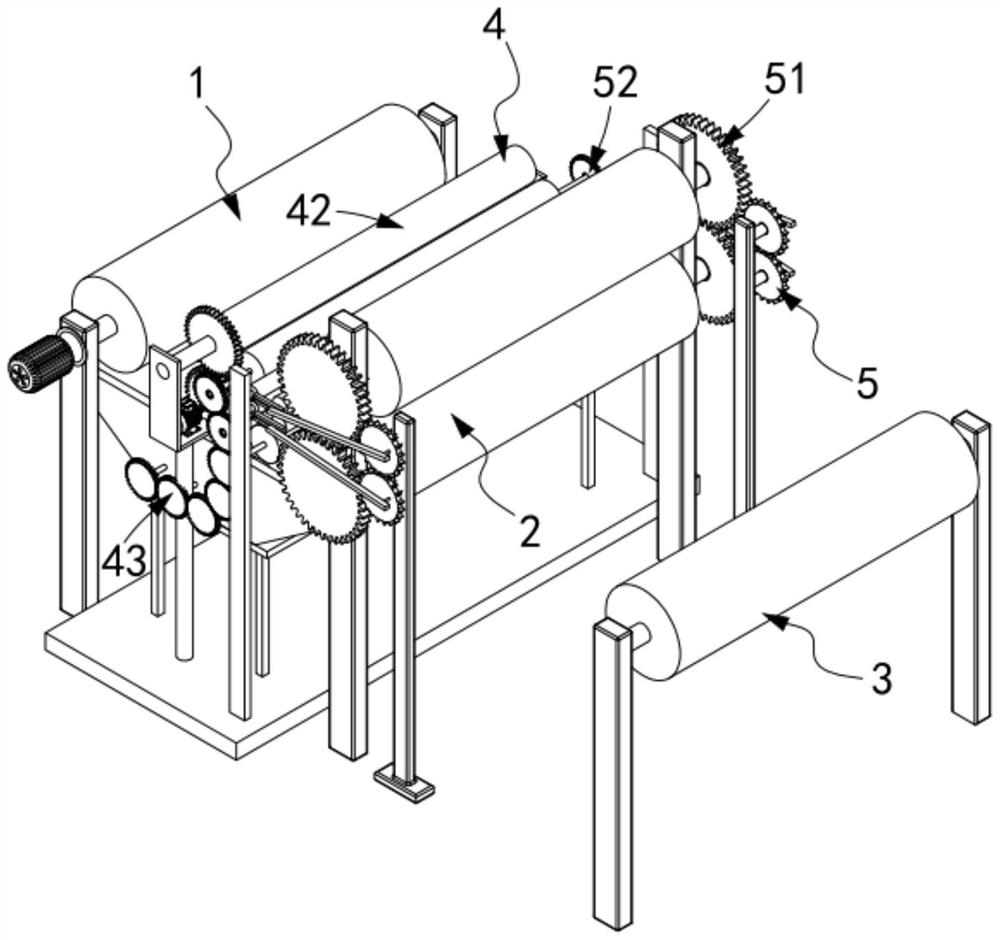
[0059] Such as figure 1 , figure 2 As shown, a diversion nonwoven composite material synthesis device includes a rubber transfer roller part 1, a pressing roller part 2 and a winding roller part 3, and also includes:

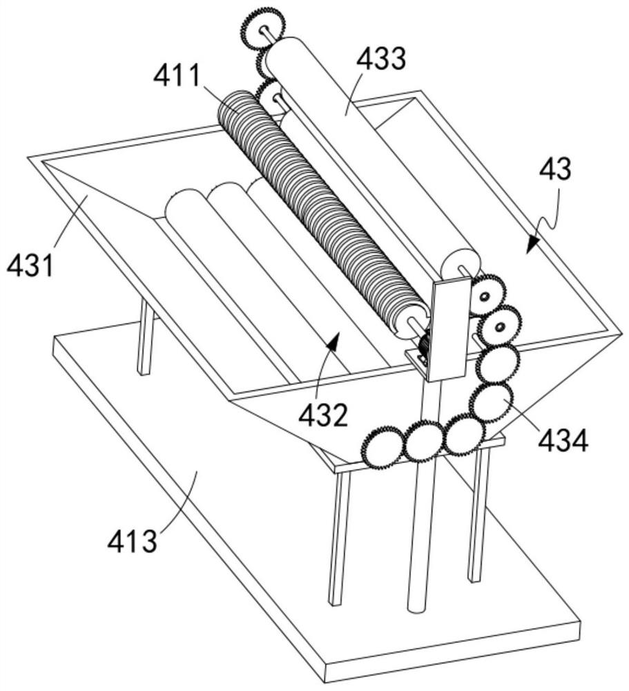
[0060] The first glue leveling mechanism 4, the first glue leveling mechanism 4 includes a scraper assembly 41 located between the glue transfer roller part 1 and the pressure roller part 2 and positioned below the flow guide net 10, located on the flow guide net 10 And between the porous isolation film 20 and the gluing assembly 42 arranged directly above the scraper assembly 41 and arranged between the scraper assembly 41 and the gluing assembly 42 in the vertical direction and used to scrape the material The waste glue on the assembly 41 is transferred to the glue transfer assembly 43 on the gluing assembly 42; and

[0061] The second glue equalizing mechanism 5, the second glue equalizing mechanism 5 includes a speed change assembly 51 synchronously drive...

Embodiment 2

[0097] Such as Figure 13 As shown, the components that are the same as or corresponding to those in the first embodiment are marked with the corresponding reference numerals in the first embodiment. For the sake of simplicity, only the differences from the first embodiment will be described below. The difference between this embodiment two and embodiment one is:

[0098] further, such as Figure 13 As shown, the gluing assembly 53 includes a second mounting frame 531 and a gluing roller 532 rotatably arranged on the second mounting frame 531 , and the gluing roller 532 is vertically along the second mounting frame 531 There are two sets of rubber-coated rollers 532 arranged in the upper direction in contact with the lower surface of the perforated isolation film 20 and the rubber-coated rollers 532 located in the lower part are arranged in contact with the upper surface of the flow guiding net 10 .

[0099] When the traditional pressure roller part 2 performs pressing work,...


PUM


Abstract

The invention relates to a diversion non-woven composite material synthesis device. The device comprises a glue transfer roller, a pressure roller and a winding roller, and further comprises a first glue leveling mechanism and a second glue leveling mechanism, wherein the first glue leveling mechanism comprises a scraping assembly, a glue feeding assembly and a glue transfer assembly; the second glue leveling mechanism comprises a variable speed assembly, a stretching assembly and a glue coating assembly; when composite operation of the pressure roller is carried out by the stretching assembly, glue is extruded onto the stretching assembly, then the extruded glue is transferred to the glue coating assembly through the stretching assembly, and the glue is transferred to the upper surface ofa diversion net and the lower surface of a perforated isolation film through the driving glue coating assembly. According to the device, the technical problems that when the composite operation is carried out between the diversion net and the perforated isolation film, water-based glue on a glue roller will flow out from gaps of the diversion net to the non-composite surface of the diversion net,then the non-composite surface of the diversion net and the perforated isolation film in contact with each other may be bonded together during winding operation, and manual separation is required inlater use are solved.

Description

technical field [0001] The invention relates to the technical field of composite flow guide nets, in particular to a device for synthesizing flow guide nonwoven composite materials. Background technique [0002] Several auxiliary materials need to be used in the production of vacuum infusion process, including release cloth, diversion net, porous film, vacuum bag film and so on. During production, the auxiliary materials are laid layer by layer on the main material. The porous film is very thin and soft, and can be naturally laid flat on gentle parts, but when the mold has a relatively steep "U"-shaped interface, the laid The porous membrane will fall off. In order to ensure that the porous membrane does not fall off, the existing production process is to spray glue on the surface of the original material, stick the porous membrane to the composite material, and then lay the diversion net. Sometimes, in some steep places, the diversion net will still fall off, and you need ...

Claims


Application Information

Patent Timeline
Patent Type & Authority Applications(China)
IPC IPC(8): B29C65/48B29C65/52B29C65/56B29C65/78B08B1/02B08B15/04B29L7/00
CPCB08B1/005B08B1/02B08B15/04B29C65/4815B29C65/521B29C65/526B29C65/56B29C65/7802B29C65/7858B29C65/7894B29C66/004B29C66/0222B29C66/032B29C66/45B29C66/876B29L2007/00
Inventor 潘利斌
Owner 潘利斌
Why Eureka
Try Eureka