
Power failure detection device

A detection device, power failure technology, applied in the direction of measuring device, measuring device casing, measuring electricity, etc., can solve the problems of reduced service life of internal electronic equipment, incompatibility between heat dissipation and sealing, poor heat dissipation of power detection device, etc., to achieve Keep clean and dry, good heat dissipation, and prolong service life

Active Publication Date: 2020-09-04
GUANGDONG POWER GRID CO LTD DONGGUAN POWER SUPPLY BUREAU +1
View PDF5 Cites 1 Cited by
  • Summary
  • Abstract
  • Description
  • Claims
  • Application Information

AI Technical Summary

Problems solved by technology

[0004] To this end, the present invention provides a power fault detection device to solve the problem of poor heat dissipation of the power detection device caused by the difficulty in compatibility with the sealing performance of the power detection device in the prior art or internal problems caused by poor sealing. The problem of reduced service life of electronic equipment

Method used


Image

  • Power failure detection device

Examples


Embodiment Construction

[0029] The implementation mode of the present invention is illustrated by specific specific examples below, and those who are familiar with this technology can easily understand other advantages and effects of the present invention from the contents disclosed in this description. Obviously, the described embodiments are a part of the present invention. , but not all examples. Based on the embodiments of the present invention, all other embodiments obtained by persons of ordinary skill in the art without making creative efforts belong to the protection scope of the present invention.

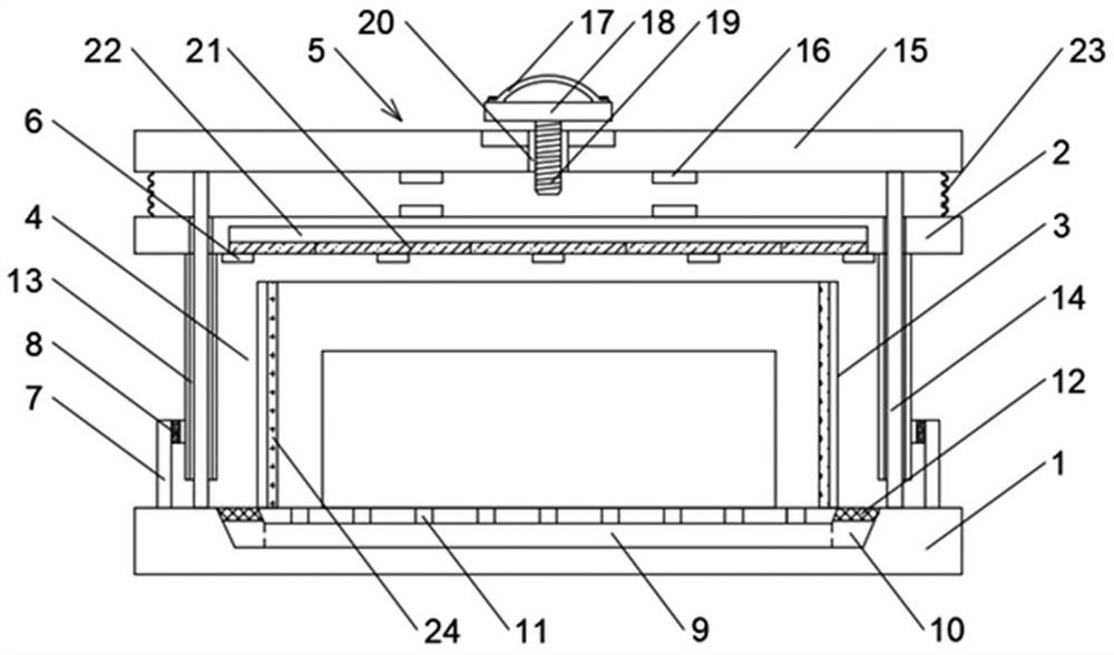
[0030] Such as figure 1 As shown, the present invention discloses a power failure detection device, including a base 1 for installing electronic detection components, and an outer shell 2 movably connected to the base 1, the bottom of the outer shell 2 is provided with an opening; the outer shell 2 can be subjected to Drive up to the open position along the direction away from the base 1, or dro...


PUM


Abstract

The invention discloses an electric power fault detection device. The device comprises a base and an outer shell, wherein the bottom of the outer shell is supported on the base so as to seal the outershell; an inner fence board located in the outer shell is installed on the base, a convection heat dissipation channel used for communicating the interior of the inner fence board with the exterior of the outer shell is formed between the inner wall of the outer shell and the outer wall of the inner fence board, and a plurality of semiconductor chilling plates located over the convection heat dissipation channel are installed on the inner wall of the outer shell. When the convection heat dissipation channel is opened; the semiconductor chilling plate enables airflow flowing downwards to be generated in the convection heat dissipation channel. Hot air rising to the top of the outer shell is sucked into the convection heat dissipation channel and is discharged; and after detection is finished, the outer shell descends to the base to close the convection heat dissipation channel, so that external air can be prevented from entering the outer shell when heat dissipation and detection are finished, the outer shell can be kept clean and dry, and the service life of the electric power detection instrument is greatly prolonged.

Description

technical field [0001] The invention relates to the technical field of power fault detection, in particular to a power fault detection device. Background technique [0002] Existing power equipment needs regular maintenance. During power maintenance, it is usually necessary to use a power detector to detect whether the power equipment is normal. Because the power line is long and there are many power equipment, the power detector often needs to perform detection work for a long time, and Since the electronic detection element will generate more heat, the long-term work of the power detector will cause the electronic detection element to work in a high temperature environment, which will not only affect the service life of the electronic detection element, but also affect the stability and detection accuracy of the electronic detection element. Negative effects, especially in summer when the temperature is higher. [0003] At present, the heat dissipation methods of electron...

Claims


Application Information

Patent Timeline
IPC IPC(8): G01R31/00G01R1/04H05K7/20
CPCG01R1/04G01R31/00H05K7/20
Inventor 程天宇郑风雷涂智豪王传旭
Owner GUANGDONG POWER GRID CO LTD DONGGUAN POWER SUPPLY BUREAU
Learn More