
Direct-driven electric workover rig

An electric workover rig, direct-drive technology, applied in drilling equipment, earthmoving, drill pipe, etc., can solve the problems of low transmission efficiency, complex transmission structure, etc. Effect of installation size

Pending Publication Date: 2020-09-04
TIANJIN DONG FANG XIAN KE GASOLINEEUM MACHINERY
View PDF4 Cites 0 Cited by
  • Summary
  • Abstract
  • Description
  • Claims
  • Application Information

AI Technical Summary

Problems solved by technology

[0004] The present invention aims at the technical defects of the prior art, and provides a direct-drive electric workover rig to solve the technical problems of conventional workover rigs with complex transmission structure and low transmission efficiency in the prior art

Method used


Image

  • Direct-driven electric workover rig
  • Direct-driven electric workover rig

Examples


Embodiment 1

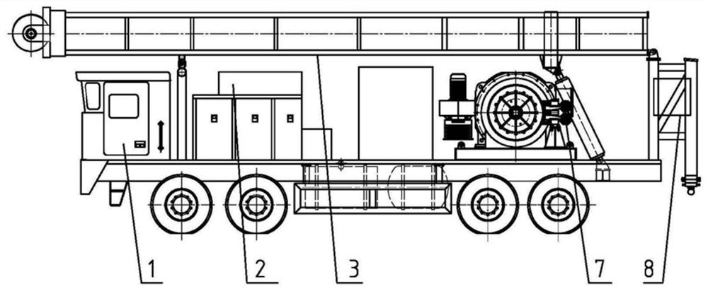
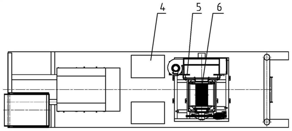
[0025] A direct drive electric workover rig, such as figure 1 , figure 2 As shown, it includes a chassis 1, a derrick 3, an AC frequency conversion disc motor 5, a winch 6, and an air control disc brake 7, wherein the chassis 1 is connected with a derrick 3, a frequency conversion disc motor 5, and a winch 6 respectively. The motor 5 is connected in transmission with the winch 6, and the winch 6 is connected with an air control disc brake 7. Among them, it also includes a braking resistor 2, an electric control cabinet 4, and an operating console 8, wherein the braking resistor 2 is arranged in the power supply circuit of the AC variable frequency disc motor 5; the electric control cabinet 4 is fixedly connected to the chassis 1, and the electric The control cabinet 4 communicates with the AC frequency conversion disc motor 5 and the air control disc brake 7 respectively; the operating console 8 is fixedly connected to the chassis 1 . Described winch 6 has drum, has Ribas r...

Embodiment 2

[0028] A direct drive electric workover rig, such as figure 1 , figure 2 As shown, it includes a chassis 1, a derrick 3, an AC frequency conversion disc motor 5, a winch 6, and an air control disc brake 7, wherein the chassis 1 is connected with a derrick 3, a frequency conversion disc motor 5, and a winch 6 respectively. The motor 5 is connected in transmission with the winch 6, and the winch 6 is connected with an air control disc brake 7.


PUM


Abstract

The invention provides a direct-driven electric workover rig. In the technical scheme, the direct-driven electric workover rig adopts the transmission mode that an AC variable frequency disk type motor directly drives a roller body and is simple in transmission and compact in structure. A winch brake system realizes the four-quadrant operation and zero-velocity load hovering function of the motorin a brake unit and brake resistor combined energy consumption brake mode. The motor can operate stably at low velocity. An energy consumption brake of a winch driving a motor frequency conversion system serves as a main brake of the winch. An auxiliary brake of the winch adopts a pneumatic control disk type brake so as to prolong the service life of brake pads and relieve the maintenance workload. A direct driven mode is adopted in the direct-driven electric workover rig, the structure of the workover rig can be simplified, and the overall weight can be reduced. Meanwhile, the direct-driven electric workover rig can be directly connected with the disk type motor, the installation size is reduced, and the transmission efficiency is improved. Through combination of the energy consumption brake and the pneumatic control disk type brake, energy consumption can be better reduced, and the braking performance can be improved.

Description

technical field [0001] The invention relates to the technical field of workover equipment, in particular to a direct-drive electric workover rig. Background technique [0002] The workover rig is the most basic and main source of power for workover and downhole operations. Conventional workover rigs generally adopt a multi-stage transmission mode of engine, transmission box, angle transmission box, and winch. The engine and transmission box also have a hydraulic torque converter. The power is finally transmitted to the steel wire rope reel through the chain and the clutch. The entire transmission chain is very complicated, and each stage of transmission has efficiency loss and wastes energy. [0003] In order to ensure the maximum lifting capacity, the engine has a large reserve and a large margin, which leads to high fuel consumption, waste of energy, and is not conducive to environmental protection. In addition, conventional winch brakes adopt belt brakes + water brakes;...

Claims


Application Information

Patent Timeline
IPC IPC(8): E21B19/00
CPCE21B19/00
Inventor 许铭尹会军雷先革田贵国彭端端于书杰潘俊姜文
Owner TIANJIN DONG FANG XIAN KE GASOLINEEUM MACHINERY
Learn More