


Quick Research
Generate reliable direction feasibility study reports for your R&D in just a few steps.

Technical Q&A
Discover and master advanced knowledge NOW. Basics, ideas, possibilities, all at once.

Find Solutions
As an expert in R&D theories, this can generate solutions to your technical problems instantly.

Evaluate Feasibility
Analyze your overall solution with one click, know your potential R&D risks in advance.

Monitor Landscape
Get weekly tech updates, stay abreast of the latest tech innovations and key insights.
Safety disassembly device for high-rise home decoration glass
A technology for dismantling devices and home decoration, which is applied in the direction of hand-held tools and manufacturing tools, etc., which can solve the problems of low efficiency and manpower consumption, and achieve the effects of high safety, avoiding glass falling, and ensuring stability
- Summary
- Abstract
- Description
- Claims
- Application Information
AI Technical Summary
Problems solved by technology
Method used
Image

Examples
Embodiment 1
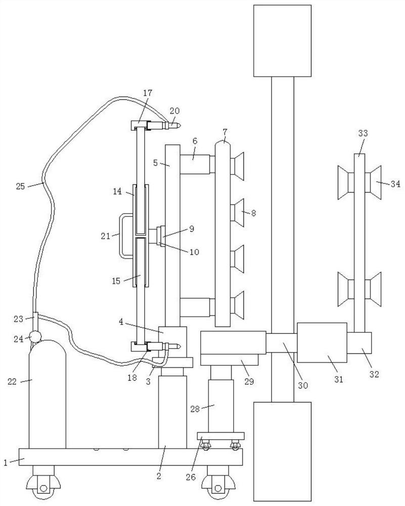
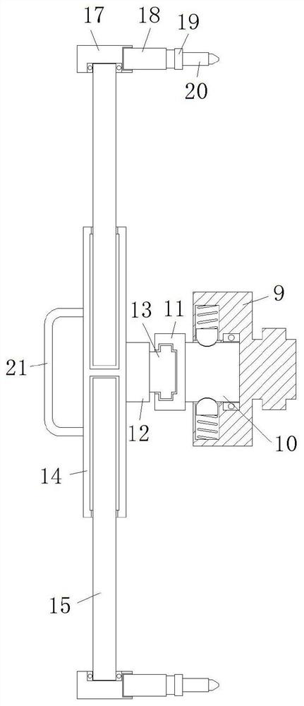
[0030] refer to Figure 1-7 , a high-rise home improvement glass safety removal device, including a base 1, universal wheels are installed at the four corners of the lower end surface of the base 1, and a cylinder-2 is fixed on one side of the top surface of the base 1 by screws, and the output end of the cylinder-2 A mounting plate 3 is fixedly connected by screws, and the top surface of the mounting plate 3 is welded with a fixing seat 4, and the top surface of the fixing seat 4 is fixedly connected with a vertical plate 5 by screws, and the side of the vertical plate 5 away from the center of the base 1 is also connected by screws An electric telescopic rod 6 is fixedly connected, and the output end of the electric telescopic rod 6 is fixedly connected with a plastic-absorbing plate 7 by screws. One side of the plate 7 is also provided with a chute, the chute is not slidably connected with a sliding block 9, one end of the sliding block 9 is rotatably connected with a fixed...
Embodiment 2
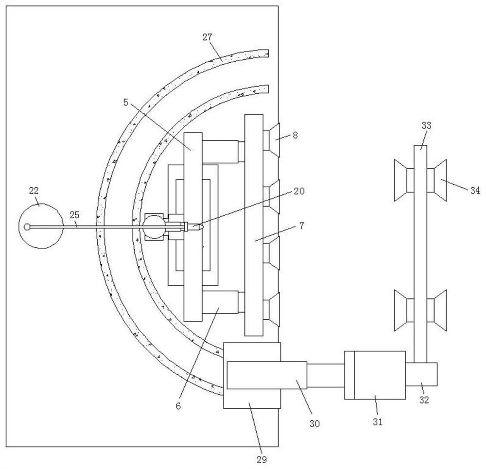
[0033] Such as figure 1 , 3 As shown in and 7, this embodiment is basically the same as Embodiment 1. Preferably, one end of the cylindrical block 31 is provided with a cylindrical hole, and the inner wall of the cylindrical hole is rotatably connected with the mounting column 32 through a rolling bearing, and the inner wall of the cylindrical hole is also provided with a groove. The groove is provided with a plurality of evenly distributed on the inner wall of the cylindrical hole in a circle, and the inner wall of the groove is slidably connected with a block 35, and an extrusion spring 36 is fixed between the block 35 and the bottom surface of the groove, and the outer wall of the mounting column 32 is also opened. There is a card slot, and the card blocks 35 are all clamped in the card slot.
[0034] The connection relationship between the fixed column 10 and the sliding block 9 is consistent with the connection relationship between the installation column 32 and the cyli...
Embodiment 3
[0037] Such as figure 1 As shown, this embodiment is basically the same as Embodiment 1. Preferably, four electric telescopic rods 6 are arranged in a rectangular shape and distributed in the extension position of the side wall of the vertical plate 5, and a plurality of suction cups 8 are arranged and distributed in a matrix. On the side wall of the blister board 7 .
[0038] In this embodiment, four electric telescopic rods 6 are provided, so that the movement of the plastic-absorbing plate 7 is more stable, and the safety when the glass is disassembled is well guaranteed.
PUM
 Abstract
Description
Claims
Application Information
 - R&D Engineer
- R&D Manager
- IP Professional
- Industry Leading Data Capabilities
- Powerful AI technology
- Patent DNA Extraction
Browse by: Latest US Patents, China's latest patents, Technical Efficacy Thesaurus, Application Domain, Technology Topic, Popular Technical Reports.
© 2024 PatSnap. All rights reserved.Legal|Privacy policy|Modern Slavery Act Transparency Statement|Sitemap|About US| Contact US: help@patsnap.com