
Cable surface washing and baking device for communication engineering

A surface cleaning and drying device technology, which is applied in the field of communication, can solve the problems of poor cleaning quality of equipment and the inability to ensure complete cleaning of impurities on the cable surface, etc., and achieve the effect of convenient cleaning and drying treatment

Inactive Publication Date: 2020-09-04
李克胜
View PDF1 Cites 0 Cited by
  • Summary
  • Abstract
  • Description
  • Claims
  • Application Information

AI Technical Summary

Problems solved by technology

[0003] The currently announced Chinese patent authorization announcement number is a cable surface cleaning device of CN110773477A. ​​Although the surface of the cable can be cleaned, the equipment is sprayed on the surface of the cable by setting a water spray device during the cleaning process, which cannot ensure Complete cleaning of impurities on the cable surface, poor cleaning quality of equipment

Method used


Image

  • Cable surface washing and baking device for communication engineering
  • Cable surface washing and baking device for communication engineering
  • Cable surface washing and baking device for communication engineering

Examples


Embodiment 1

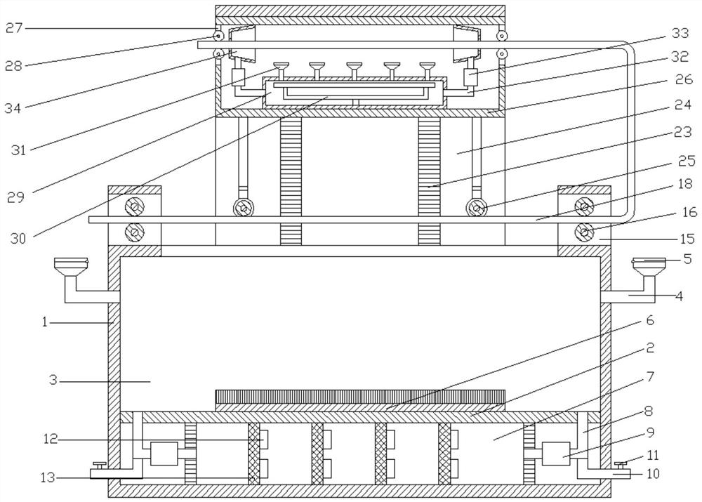
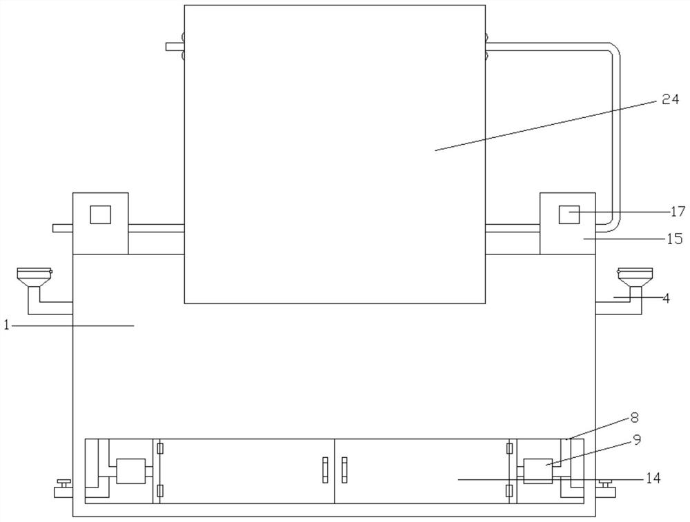
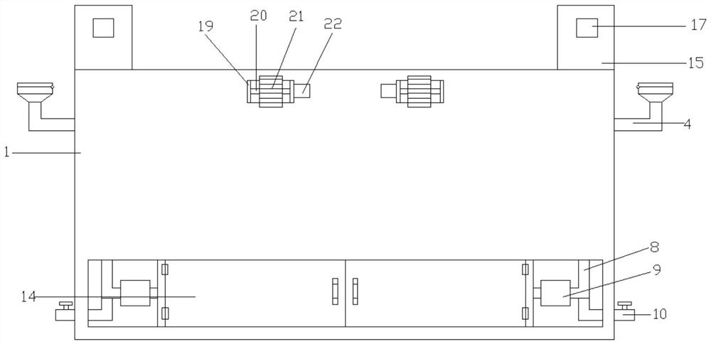
[0026] refer to Figure 1~4 , in an embodiment of the present invention, a cable surface cleaning and drying device for communication engineering, including a box body 1, the lower end of the box body 1 is provided with a partition 2, and the partition board 2 divides the upper end of the box body 1 into a cleaning chamber 3. There are water inlets 4 on the left and right sides of the upper end of the cleaning chamber 3, and the upper side of the water inlet 4 is connected with a sealing plate 5 through a hinge, which can facilitate the addition of cleaning solution to the inside of the cleaning chamber 3. The middle end of the bottom of the cleaning chamber 3 A cleaning brush 6 is fixedly installed to scrub the surface of the cable.

[0027] The middle part of the lower side of the dividing plate 2 is provided with a filter chamber 7, the left and right sides of the filtering chamber 7 are connected with the bottom dividing plate 2 of the cleaning chamber 3 through a connecti...

Embodiment 2

[0033] The difference from Embodiment 1 is that a drain pipe 10 is installed at the outer end of the lower side of the connecting pipe 8, and a control valve 11 is installed on the drain pipe 10 outside the box body 1, which can facilitate the discharge of the cleaning solution, which can facilitate the equipment Proceed to replace the cleaning solution.


PUM


Abstract

The invention relates to the field of communication, in particular to a cable surface washing and baking device for communication engineering. The cable surface washing and baking device comprises a box body. A partition plate is arranged at the lower end in the box body. The upper end of the box body is divided into a washing cavity through the partition plate. A washing hairbrush is fixedly installed at the middle end of the bottom of the washing cavity. Connecting covers are arranged at the left end and the right end of the upper side of the box body correspondingly. First gears are arranged at the upper end and the lower end in each connecting cover through connecting shafts. Connecting bases are arranged at the left ends and the right ends of the front side and the rear side of the box body correspondingly. Second gears are connected into the connecting bases through rotating shafts. Racks are arranged on the outer sides of the second gears in an engaged manner. The racks are installed on the left sides and the right sides of the front end and the rear end of the inner wall of a supporting frame. A baking cavity is formed in the middle end of the top of the supporting frame. First connecting rollers are arranged at the left end and the right end of the lower side of the baking cavity. A heating cavity is formed in the bottom of the baking cavity. A heating rod is installedin the heating cavity. A plurality of spraying heads are uniformly arranged on the upper side of the heating rod. The cable surface washing and baking device can effectively wash the surface of a cable completely, and therefore can ensure cleanness of the surface of the cable.

Description

technical field [0001] The invention relates to the communication field, in particular to a cable surface cleaning and drying device for communication engineering. Background technique [0002] The cable is usually a rope-like cable twisted by several or several groups of conductors (at least two in each group). Each group of conductors is insulated from each other and is often twisted around a center. Insulating covering. Cables have the characteristics of internal energization and external insulation. In the process of communication engineering construction, it is often necessary to use cables for equipment connection and power supply processing. [0003] The currently announced Chinese patent authorization announcement number is a cable surface cleaning device of CN110773477A. ​​Although the surface of the cable can be cleaned, the equipment is sprayed on the surface of the cable by setting a water spray device during the cleaning process, which cannot ensure Complete c...

Claims


Application Information

Patent Timeline
IPC IPC(8): B08B1/02B08B3/04B08B3/14F26B13/04F26B21/00F26B21/04
CPCB08B3/041B08B3/14F26B13/001F26B21/001F26B21/004F26B21/04B08B1/20
Inventor 李克胜
Owner 李克胜
Learn More