Cleaning device for circuit board electroplateing processing and application method of cleaning device
A technology for cleaning devices and circuit boards, which is applied in the direction of cleaning methods using tools, cleaning methods using liquids, cleaning methods and utensils, etc., can solve problems such as poor cleaning effect, and achieve the effect of clean cleaning effect and thorough cleaning effect.
- Summary
- Abstract
- Description
- Claims
- Application Information
AI Technical Summary
Problems solved by technology
Method used
Image
Examples
Embodiment 1
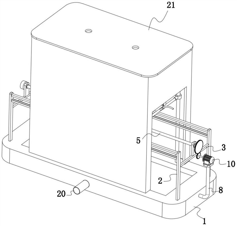
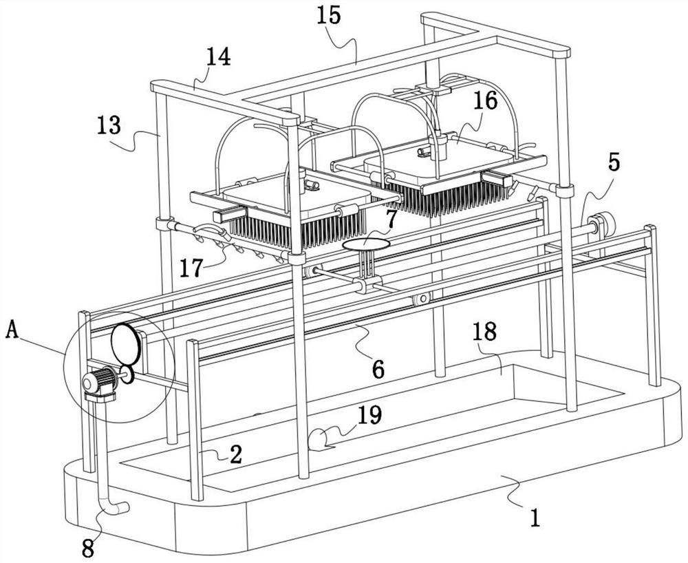
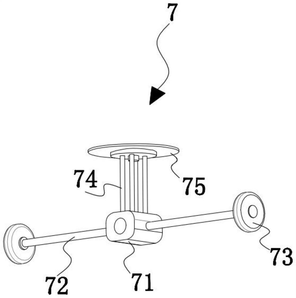
[0032] refer to Figure 1-7 , a cleaning device for circuit board electroplating processing and its use method, comprising a base 1, two side plates 2 correspondingly arranged are fixedly installed on both sides of the upper surface of the base 1, and each two corresponding side plates 2 are fixed A crossbar 3 is provided, and a fixed plate 4 is fixedly installed on the upper surface of the crossbar 3. A threaded rod 5 is rotatably installed between the two fixed plates 4. Two sides parallel to the length direction of the base 1 are arranged on both sides above the base 1. rail 6, and both ends of each side rail 6 are fixedly connected to the corresponding side plate 2, an adsorption mechanism 7 is threaded on the threaded rod 5, and one end of the threaded rod 5 passes through the fixed plate 4 and is fixedly connected with a drive mechanism;
[0033] The upper surface of the base 1 between the four side plates 2 is fixedly installed with four support columns 13 distributed ...
Embodiment 2
[0043] refer to Image 6 , as another preferred embodiment of the present invention, the difference from Embodiment 1 is that the water spray mechanism 17 includes a fixed sleeve 171, a water pipe 172, a water inlet connection pipe 173, a water outlet pipe 174, a nozzle 175, and a second connection hose 176 , a fixed sleeve 171 is fixedly installed on each supporting column 13, a water pipe 172 is installed between every two corresponding fixed sleeves 171, and a water inlet connecting pipe 173 is fixedly installed on the water pipe 172, and the water inlet connecting pipe 173 A second connecting hose 176 is fixedly connected to the top, and several water outlet pipes 174 are fixedly distributed along the length direction on the water pipe 172 , and each water outlet pipe 174 is threaded with a shower head 175 .
[0044] When the device is in use, the second connecting hoses 176 on the two water spray mechanisms 17 are all fixedly connected to the water supply mechanism. The ...
Embodiment 3
[0046] refer to Figure 1-2 As another preferred embodiment of the present invention, the difference from Embodiment 1 is that a water tank 18 is formed on the upper surface of the base 1, and a through hole 19 is formed on the bottom side wall of the water tank 18, and a water outlet pipe 20 is inserted in the through hole 19. The bottom of the water tank 18 is fixedly provided with a slope inclined toward the through hole 19 side, and the upper surface of the base 1 is fixedly installed with a shell 21 covering the internal mechanism.
[0047] When the device is in use, the shell 21 is used to block the splashing water droplets during the cleaning process, so as to prevent the water droplets from splashing and polluting the workshop during the cleaning process. In addition, by setting the water tank 18, the blocked water droplets and the water flow generated during the cleaning process will be absorbed by the water tank. 18 is collected, because a slope is provided at the bo...
PUM
 Abstract
Description
Claims
Application Information
 - R&D
- Intellectual Property
- Life Sciences
- Materials
- Tech Scout
- Unparalleled Data Quality
- Higher Quality Content
- 60% Fewer Hallucinations
Browse by: Latest US Patents, China's latest patents, Technical Efficacy Thesaurus, Application Domain, Technology Topic, Popular Technical Reports.
© 2025 PatSnap. All rights reserved.Legal|Privacy policy|Modern Slavery Act Transparency Statement|Sitemap|About US| Contact US: help@patsnap.com


