High-voltage generator based on MOS transistor series discharge

A technology of high-voltage generator and MOS tube, which is applied to the components of electrical measuring instruments, instruments, and measuring electronics. It can solve problems such as waveform distortion and reduce the output capacity of the booster, so as to achieve reasonable value and reduce circuit response. speed effect

Active Publication Date: 2020-09-01
任守华
View PDF9 Cites 1 Cited by
  • Summary
  • Abstract
  • Description
  • Claims
  • Application Information

AI Technical Summary

Problems solved by technology

[0003] Resistor step-down brings two serious problems: one is that in the boost stage, the resistor becomes the load of the booster, which not only increases extra heat, but also reduces the output capability of the b

Method used


Image

  • High-voltage generator based on MOS transistor series discharge
  • High-voltage generator based on MOS transistor series discharge

Examples


Embodiment

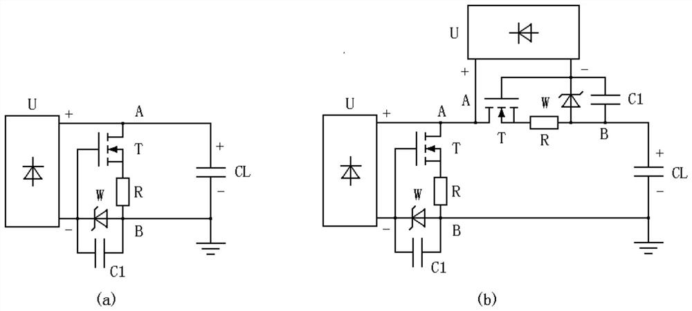
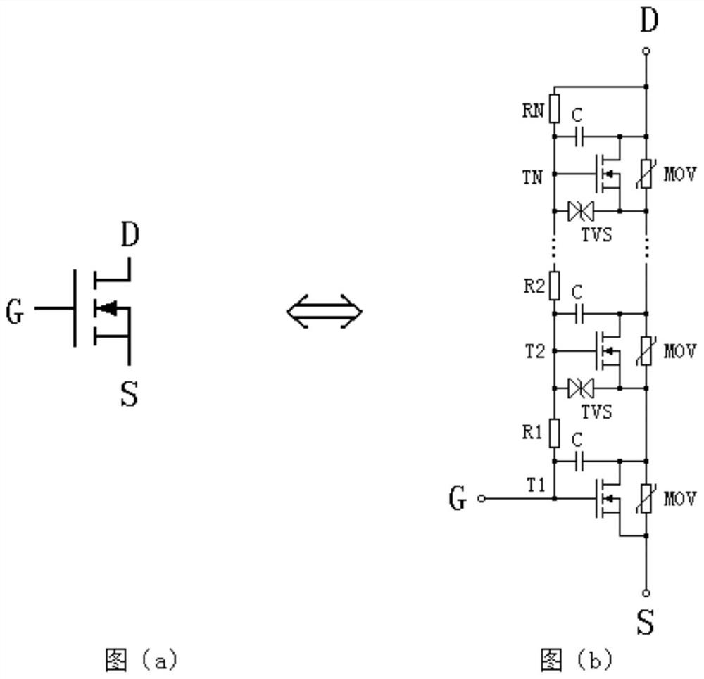
[0043] A high-voltage generator based on MOS tube series discharge, such as figure 1 As shown, it includes MOS tube series discharge circuit T, booster U, current limiting resistor R, voltage stabilizing element W and anti-interference capacitor C1, such as figure 2As shown in (b), the MOS tube series discharge circuit T includes N voltage equalizing resistors and N series connected MOS tubes. The N MOS tubes are respectively T1, T2, ..., TN, and the N voltage equalizing resistors are respectively R1 , R2, ..., RN, in the above N MOS transistors, the source of Ti is electrically connected to the drain of Ti+1, the gate of Ti is electrically connected to the first end of Ri, and the second end of Ri is electrically connected to Ti+1 The gate of 1 is electrically connected, the gate of TN is electrically connected to the first end of RN, the second end of RN is electrically connected to the source of TN, and a capacitor C is connected in parallel between the gate and source of ...


PUM


Abstract

The invention discloses a high-voltage generator based on MOS transistor series discharge, belongs to the technical field of electronic and high-voltage measurement, and aims at solving the technicalproblem of how to overcome the defect of voltage reduction of a traditional resistor. The high-voltage generator comprises a MOS transistor series discharge circuit which comprises N voltage-sharing resistors and N MOS transistors connected in series, a capacitor C is connected in parallel between the grid electrode and the source electrode of each MOS transistor, and a voltage-limiting protectionelement MOV is connected in parallel between the source electrode and the drain electrode of each MOS transistor; the first end of the booster is electrically connected with the source electrode of the TN and is connected with the output A, and the second end is electrically connected with the grid electrode of the T1; the first end of the current-limiting resistor R is electrically connected with the drain electrode of the T1, and the second end is connected with the output B; the first end of the voltage stabilizing element W is electrically connected with the grid electrode of the T1; andthe first end of the anti-interference capacitor C1 is electrically connected with the grid electrode of T1, and the second end of the anti-interference capacitor C1 is electrically connected with thesecond end of the voltage stabilizing element W and connected with output B.

Description

technical field [0001] The invention relates to the technical field of electronics and high-voltage measurement, in particular to a high-voltage generator based on MOS tube series discharge. Background technique [0002] High-voltage measurement requires various DC or AC high-voltage generators, and many measured objects have large capacitance, such as high-voltage cables or capacitors. When using DC measurement, it is necessary to manually discharge the measured object after the measurement is completed. However, when performing ultra-low frequency AC high voltage measurement, there is always a charging and discharging process of the measured capacitor. The current electronic switch boost technology is mature, but the biggest problem encountered is that the booster can only boost the voltage, not step down. Therefore, the current DC high voltage generator does not consider the problem of capacitive load step-down, but the resistance method is generally used to realize the...

Claims


Application Information

Patent Timeline
IPC IPC(8): H02M3/158H02M1/32G01R1/00
CPCG01R1/00H02M1/32H02M3/158H02M1/322
Inventor 任守华任翔
Owner 任守华
Why Eureka
Try Eureka