
Liquid discharging device, filtering system and semiconductor processing equipment

A technology of drainage device and filtration system, applied in semiconductor/solid-state device manufacturing, filtration separation, fixed filter element filter, etc., can solve the problem that the reactant cannot be effectively removed, there is no fixed flow direction, and the reactant cannot effectively enter the circulating filtration system problems

Active Publication Date: 2020-09-01
厦门通富微电子有限公司
View PDF6 Cites 1 Cited by
  • Summary
  • Abstract
  • Description
  • Claims
  • Application Information

AI Technical Summary

Problems solved by technology

However, for an etching machine with an open tank structure, it cannot effectively remove reactants
In addition, for other monolithic etching machines, the circulating filtration method is that the liquid medicine enters from the top of the tank - flows out from the bottom of the tank - circulation pump - filter barrel filter - enters the tank, and the liquid in the tank will appear irregular Flow direction, which is easy to form turbulent flow, so that the reactants cannot effectively enter the circulating filtration system

Method used


Image

  • Liquid discharging device, filtering system and semiconductor processing equipment
  • Liquid discharging device, filtering system and semiconductor processing equipment
  • Liquid discharging device, filtering system and semiconductor processing equipment

Examples


Embodiment Construction

[0031] In order to enable those skilled in the art to better understand the technical solutions of the present invention, the present invention will be further described in detail below in conjunction with the accompanying drawings and specific embodiments.

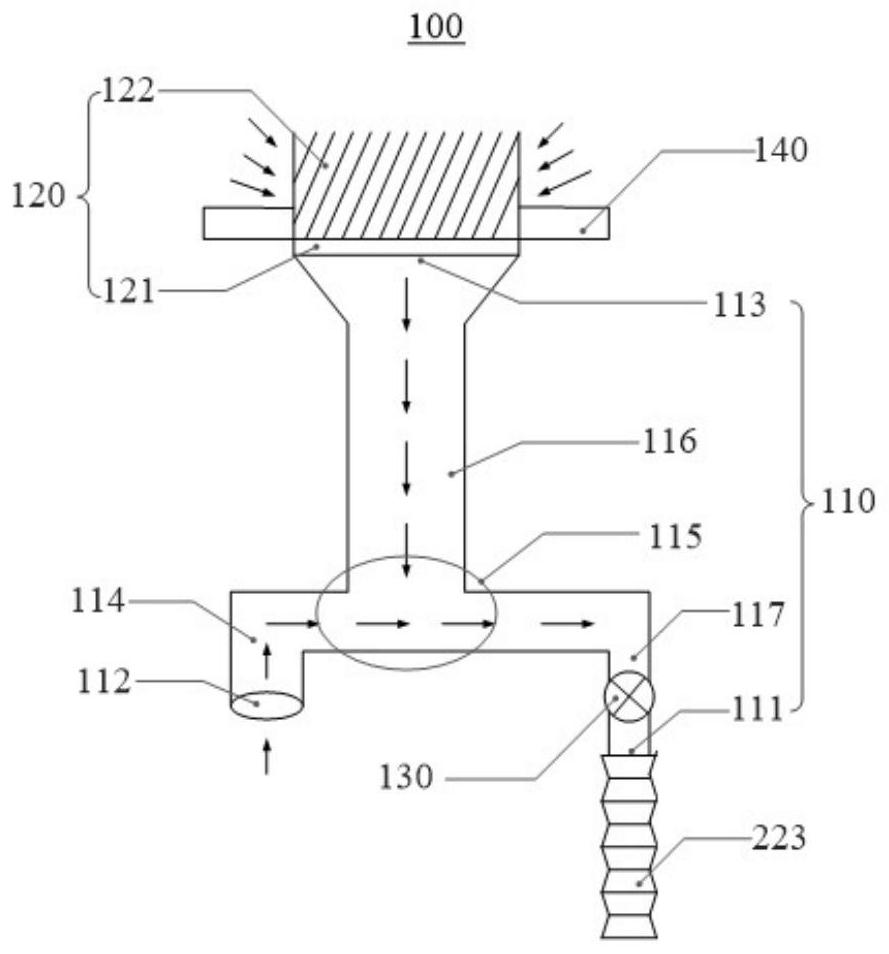
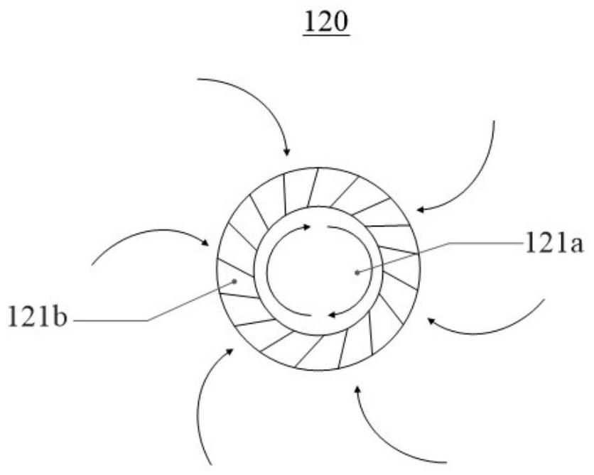
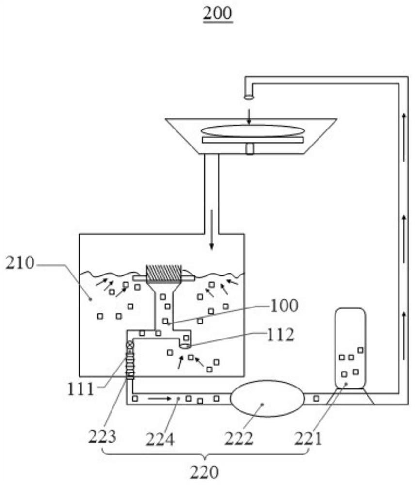
[0032] Such as figure 1 As shown, one aspect of the present invention provides a liquid discharge device 100, the liquid discharge device 100 includes a siphon 110 and a guide pipe 120, the siphon 110 is provided with a liquid outlet 111, a first liquid inlet 112 and a first The second liquid inlet 113 that the liquid inlet 112 communicates with the liquid outlet 111, the guide tube 120 communicates with the second liquid inlet 113, wherein, when the liquid outlet 111 is subjected to suction force, the first liquid inlet 112 and the second liquid inlet 113 are connected. A pressure difference is formed between the second liquid inlets 113 to form a siphon force at the second liquid inlet 113, and the guide pipe 120 guides...


PUM


Abstract

The invention provides a liquid discharging device, a filtering system and semiconductor processing equipment, and belongs to the technical field of semiconductor processing. The liquid discharging device comprises a siphon and a guide pipe; the siphon is provided with a liquid outlet, a first liquid inlet and a second liquid inlet communicated with the first liquid inlet and the liquid outlet respectively, the guide pipe is communicated with the second liquid inlet, and when the liquid outlet is subjected to suction force, a pressure difference is formed between the first liquid inlet and thesecond liquid inlet so as to form siphon force at the second liquid inlet; and the guide pipe guides the to-be-filtered liquid under the action of siphon force, and then the to-be-filtered liquid enters the second liquid inlet and is discharged through the liquid outlet. According to the liquid discharging device provided by the invention, to-be-filtered liquid can flow into the siphon in a directional manner; the liquid to be filtered is effectively prevented from forming turbulent flow without a fixed flow direction, so that the to-be-filtered liquid effectively enters a subsequent circulating filtration system, the liquid discharge efficiency and the removal rate of reactants in the to-be-filtered liquid are improved, and the treatment effect of the semiconductor treatment equipment isfurther improved.

Description

technical field [0001] The invention belongs to the technical field of semiconductor processing, and in particular relates to a liquid discharge device, a filtering system and a semiconductor processing equipment. Background technique [0002] At present, the etching process in the semiconductor manufacturing industry uses chemical etching machines. After chemical etching, reactants will be suspended in the chemical solution. If the reactants are not removed, they will adhere to the surface of the product and affect the etching effect. . [0003] However, the main groove etching machines in the industry have an inner and outer groove structure and an open groove body structure. For an etching machine with an inner and outer groove structure, the overflow of the inner groove - the outflow of the outer groove - the circulating pump - the filtration of the filter barrel - The reactant is removed by the circulation filtration method entering the inner tank, that is, the reactan...

Claims


Application Information

Patent Timeline
IPC IPC(8): H01L21/67B01D29/90
CPCH01L21/67075B01D29/90
Inventor 张雷
Owner 厦门通富微电子有限公司
Learn More