
Liquid suction and drainage valve and working method thereof

A liquid discharge valve and liquid suction valve technology, applied in the field of liquid suction and discharge valves, can solve the problems of many types of parts and styles, difficult installation and maintenance, and large inventory of spare parts, and achieve the effects of compact structure, reduced cavitation, and simple guiding structure

Pending Publication Date: 2020-09-01
BEIJING HUAHAI MACHINERY
View PDF0 Cites 1 Cited by
  • Summary
  • Abstract
  • Description
  • Claims
  • Application Information

AI Technical Summary

Problems solved by technology

[0002] The existing suction and discharge valves and related connectors for plunger pumps are all independent structural designs, which have disadvantages such as difficult installation and maintenance, many types of parts and styles, non-interchangeable parts, and large inventory of spare parts.

Method used


Image

  • Liquid suction and drainage valve and working method thereof

Examples


Embodiment Construction

[0021] In order to make the purpose, content, and advantages of the present invention clearer, the specific implementation manners of the present invention will be further described in detail below in conjunction with the accompanying drawings and embodiments.

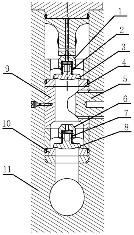
[0022] The invention provides a liquid suction and discharge valve, which is used to realize the functions of a plunger pump used in a pumping station that supplies a power source to a coal mine hydraulic support to suck in and discharge media such as water or emulsion, including: a liquid discharge valve guide seat 1, a liquid discharge valve Valve spring 2, discharge valve core 3, discharge valve seat 4, plunger 5, suction valve guide seat 6, suction valve spring 7, suction valve core 8, sleeve 9, suction valve seat 10 and pump Head shell 11;

[0023] The drain valve guide seat 1 is used to guide the movement of the drain valve core 3; the drain valve spring 2 is used to automatically reset the drain valve core 3; th...


PUM


Abstract

The invention relates to a liquid suction and drainage valve and a working method thereof, and belongs to the technical field of coal mines. The liquid suction and discharge valve is linearly arranged, so that the structure is more compact; the guide structure is simple and the friction force is smaller; two sides of a valve seat can be used, so that the service life is longer; the valve seat is in clearance fit with a mounting hole and is convenient to replace; due to medium-flow-rate design, cavitation is reduced; and a liquid suction valve and a liquid discharge valve can be interchanged for use, so that fewer spare parts are realized.

Description

technical field [0001] The invention belongs to the technical field of coal mines, and in particular relates to a liquid suction and discharge valve and a working method thereof. Background technique [0002] Existing plunger pump suction and discharge valves and related connectors are all independent structural design forms, which have the disadvantages of difficult installation and maintenance, many types of parts and styles, non-interchangeable parts, and large inventory of spare parts. Contents of the invention [0003] (1) Technical problems to be solved [0004] The technical problem to be solved by the present invention is: how to design a liquid suction and discharge valve with simple structure, long service life and convenient maintenance. [0005] (2) Technical solutions [0006] In order to solve the above technical problems, the present invention provides a suction and discharge valve, comprising: a discharge valve guide seat 1, a discharge valve spring 2, a ...

Claims


Application Information

Patent Timeline
IPC IPC(8): F04B53/10F04B53/16F04B53/22
CPCF04B53/109F04B53/1087F04B53/16F04B53/22
Inventor 杜建华董士刚杨淑芳
Owner BEIJING HUAHAI MACHINERY
Learn More