
Gas extraction hole drainage method

A technology for gas extraction and extraction holes, which is applied in the directions of gas discharge, drainage, and extraction of fluids, etc., can solve the problems of inability to timely extraction of drilling holes, frequent movements of automatic water dischargers, easy blockage and damage, etc., and achieve drainage costs. Low cost, simple and easy-to-control drainage process

Active Publication Date: 2020-09-01
四川川煤华荣能源有限责任公司
View PDF15 Cites 3 Cited by
  • Summary
  • Abstract
  • Description
  • Claims
  • Application Information

AI Technical Summary

Problems solved by technology

[0004] Traditionally, the automatic water release device is used to discharge the water in the upward hole, and the automatic water release device is automatically controlled by its buoyancy, which is costly, and when the water gushing in the hole is large, the automatic water release device operates frequently, which is prone to blockage and damage. Therefore, in In the drainage holes with large water gushing volume, the drainage system is not connected, and the drainage is carried out after the water volume drops significantly. This will cause some boreholes with large water gushing and gas gushing volumes to be unable to be drained in time

Method used


Image

  • Gas extraction hole drainage method
  • Gas extraction hole drainage method
  • Gas extraction hole drainage method

Examples


Embodiment Construction

[0039] Below in conjunction with accompanying drawing and embodiment the present invention is described further as follows:

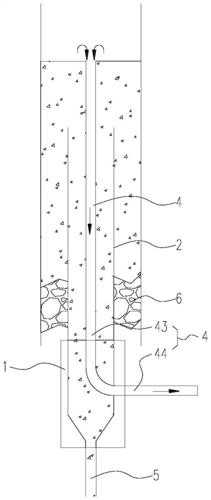
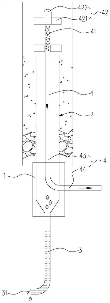
[0040] The gas drainage hole drainage method, step 1, burying the sealing buried pipe 2 in the drainage hole upward;

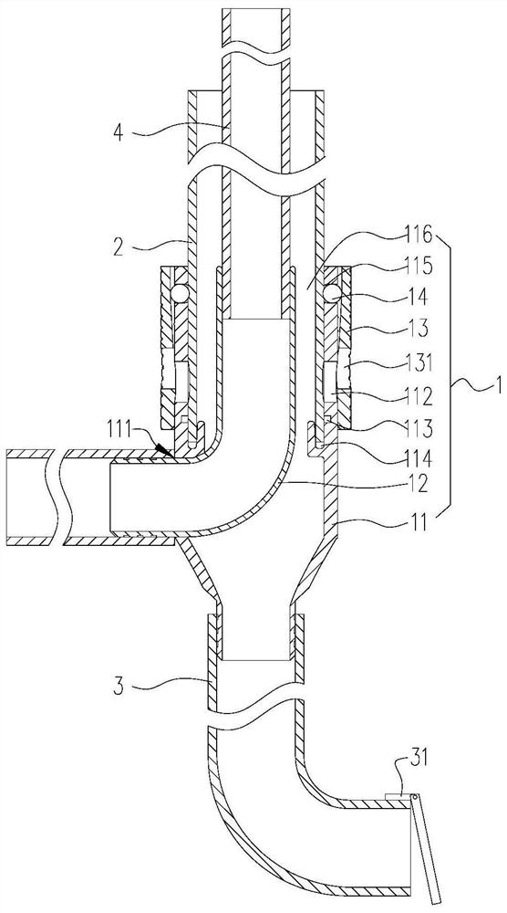
[0041] Step 2. Assemble the drainage pipe 3 and the exhaust pipe 4 using the connecting device 1 arranged at the bottom of the sealed buried pipe 2:

[0042] Such as figure 2 and image 3 As shown, the connecting device 1 includes an outer tube 11 and an inner tube 12; the two ends of the outer tube 11 are connected, one end is a plug-in end, and the other end is a connecting end; An orifice 111 through which the inner cavity of the tube 11 penetrates radially; the inner tube 12 is L-shaped, one end is a plug-in end, and the other end is a connecting end; the inner tube 12 is plugged into the outer tube 11, An insertion space 116 is provided between the inner wall and the outer wall of the inner tube 12; the insertion end of the inn...


PUM


Abstract

The invention provides a gas extraction hole drainage method and belongs to the field of coal mine gas extraction. The gas extraction hole drainage method aims to achieve that drainage and exhaust ofan upward hole are synchronously conducted, so that gas extraction is conducted in time. The gas extraction hole drainage method comprises the following steps that firstly, a hole sealing embedded pipe is buried in the upward extraction hole; secondly, a connection device arranged at the bottom end of the hole sealing embedded pipe is utilized to assemble a drainage pipe and an exhaust pipe; thirdly, an extraction system is started, gas in the extraction hole is extracted out through an exhaust passage, and water in the extraction hole is discharged through a drainage passage under the actionof weight. According to the gas extraction hole drainage method, by means of the connecting device, the drainage pipe and the hole sealing embedded pipe are made to communicate to form the drainage passage; by means of the connecting device, the exhaust pipe is inserted into the hole sealing embedded pipe to form the exhaust passage; by means of design of an inner pipe and an outer pipe of the connecting device, the drainage passage and the exhaust passage are mutually independent and do not interfere each other, gas-water separation is achieved, so that gas extraction and drainage of an extraction hole can be simultaneously conducted, and the purpose of conducting gas extraction in time is achieved; and gravity drainage is conducted, so that control is easy, and cost is low.

Description

technical field [0001] The invention belongs to the field of gas drainage in coal mines, in particular to a drainage method for gas drainage holes. Background technique [0002] During coal mining, it is necessary to drill gas drainage holes on the roadway surface to extract the gas in the coal seam, so as to ensure the safety of coal mining. During gas drainage, according to the drilling angle, it is divided into upward holes, downward holes and horizontal holes. The holes extending downward from the horizontal surface are called downward holes, and the holes extending upward from the horizontal surface are called upward holes. [0003] At present, deep hole drainage is usually used for gas drainage. Drainage holes are set in the rock formation and extend to the deep part of the coal seam. Water seepage, water gushing and drilling operation water from the rock formation and coal seam around the drainage hole are poured into the drainage. inside the hole. The drainage hole...

Claims


Application Information

Patent Timeline
IPC IPC(8): E21F7/00E21F16/00E21B43/00E21B33/13
CPCE21B33/13E21B43/00E21B43/006E21F7/00E21F16/00
Inventor 杜海军刘海涛王小兵李超刘正平冯长春柳永红董兴洪孙光全邓德智何颜远郭进刘光忠田茂建陈伟蒋梦军李华
Owner 四川川煤华荣能源有限责任公司
Learn More