
Device for expanding excavation and pre-reinforcement of tunnel lateral surrounding rock

A pre-reinforcement and surrounding rock technology, applied in the installation of bolts, mining equipment, earth-moving drilling, etc., can solve the problems of low shear strength of glass fiber, waste of money and manpower, engineering accidents, etc., to achieve protection integrity, Cost saving and effect of improving tensile strength

Inactive Publication Date: 2020-09-01
中交四公局第一工程有限公司 +2
View PDF9 Cites 0 Cited by
  • Summary
  • Abstract
  • Description
  • Claims
  • Application Information

AI Technical Summary

Problems solved by technology

[0002] In the current technical field of tunnel engineering, anchor bolts are often used for pre-reinforcement in the lateral excavation of surrounding rock, but in the specific construction process, it is found that although the pre-reinforcement effect of anchor bolts on surrounding rock is remarkable, but due to the It has high shear strength and is not easy to break during excavation, which will lead to a longer construction period and a waste of funds and manpower; glass fiber is a kind of reinforced material with glass fiber, glass cloth, felt, yarn and tape. It is a composite material made of resin as a matrix binder. Its main characteristics are high tensile strength, easy cutting without sparks, low shear strength, and easy digging, etc.
However, when laying glass fiber, due to the low shear strength of glass fiber, it is easy to break during the laying process, and it is also easy to cause damage to the internal glass fiber during spraying, resulting in failure to check in time, prone to engineering accidents and property losses

Method used


Image

  • Device for expanding excavation and pre-reinforcement of tunnel lateral surrounding rock
  • Device for expanding excavation and pre-reinforcement of tunnel lateral surrounding rock

Examples


Embodiment Construction

[0020] In describing the present invention, it should be understood that the terms "center", "longitudinal", "transverse", "upper", "lower", "front", "rear", "left", "right", " Orientations or positional relationships indicated by "vertical", "horizontal", "top", "bottom", "inner", "outer", "axial", "radial", etc. are based on the orientation or position shown in the drawings The relationship is only for the convenience of describing the present invention and simplifying the description, but does not indicate or imply that the referred device or element must have a specific orientation, be constructed and operated in a specific orientation, and thus should not be construed as a limitation of the present invention.

[0021] In addition, the terms "first" and "second" are used for descriptive purposes only, and cannot be interpreted as indicating or implying relative importance or implicitly specifying the quantity of indicated technical features. Thus, a feature defined as "fir...


PUM

PropertyMeasurementUnit
The inside diameter ofaaaaaaaaaa

Abstract

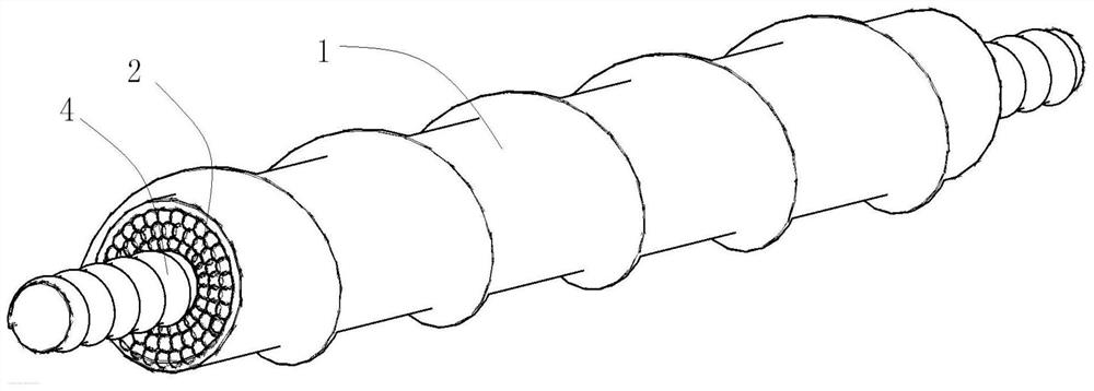
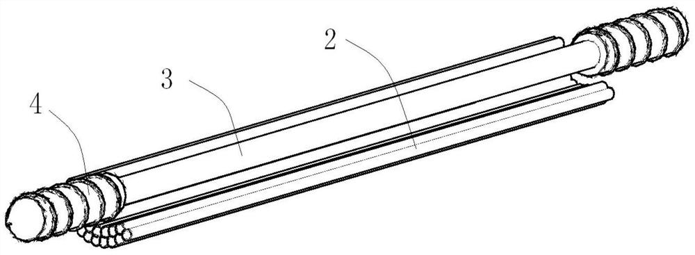
The invention provides a device for expanding excavation and pre-reinforcement of tunnel lateral surrounding rock. The device comprises a pipe barrel, a glass fiber pipe, a central connecting rod andspiral reinforcements; the pipe barrel is a PVC pipe made of PVC; the central connecting rod is positioned in the internal axis of the pipe barrel; the glass fiber pipe is filled in a gap between thepipe barrel and the central connecting rod and is made of composite material formed through association of fiber glass, glass cloth, a felt, yarn and a belt as reinforcing material and synthetic resinas the basis material; and the spiral reinforcements are arranged at the two ends of the central connecting rod separately. According to the device, an external sleeve is spiral, the frictional forcewith the surrounding rock is better increased after grouting externally, and integrity of the glass fiber pipe can be well protected; the internal glass fiber pipe greatly improves the drawing resistance of the device, and the spiral reinforcements are arranged at the two ends of the central connecting rod to facilitate strong anchoring, and the bearing overall coordination of the device is improved.

Description

technical field [0001] The invention relates to the technical field of tunnel engineering construction, in particular to a device for pre-reinforcement of tunnel lateral surrounding rock expansion and excavation. Background technique [0002] In the current technical field of tunnel engineering, anchor bolts are often used for pre-reinforcement in the lateral excavation of surrounding rock, but in the specific construction process, it is found that although the pre-reinforcement effect of anchor bolts on surrounding rock is remarkable, but due to the It has high shear strength and is not easy to break during excavation, which will lead to a longer construction period and a waste of funds and manpower; glass fiber is a kind of reinforced material with glass fiber, glass cloth, felt, yarn and tape. Resin is used as a matrix binder to form a composite material. Its main characteristics are high tensile strength, easy cutting without sparks, low shear strength, and easy digging....

Claims


Application Information

Patent Timeline
IPC IPC(8): E21D21/00
CPCE21D21/0033E21D21/0066E21D21/0006
Inventor 杨伟光包特门白乙拉郑永飞傅鹤林王江滔董辉赵耀刘俊奇周琦郝鹏史成铭姚景武吕鑫
Owner 中交四公局第一工程有限公司
Learn More