
Mechanical positioning mechanism, lockset and electromagnetic locking system

A mechanical positioning and electromagnetic technology, applied in building locks, lock applications, electric matching locks, etc., can solve the problems of large space occupation, inconvenient maintenance and installation, low spring coefficient of return spring, etc., to achieve unique structure, easy installation and Easy maintenance and small space occupation

Pending Publication Date: 2020-09-01
CHONGQING IND POLYTECHNIC COLLEGE
View PDF6 Cites 4 Cited by
  • Summary
  • Abstract
  • Description
  • Claims
  • Application Information

AI Technical Summary

Problems solved by technology

[0004] However, the existing locking structure needs to be controlled by the two parts of the locking and unlocking executive electrical components, so the design of electronic devices on the logic gate requires a large cost, and the locking and unlocking are controlled by two independent systems , the cost of production and maintenance is high, and the dead bolt and power control system in the existing lockset are at the same horizontal line, which takes up a lot of space, and it is inconvenient to overhaul and install with many card slots; after the electromagnetic lock is used for a long time, the elasticity of the return spring The coefficient is low, which makes the deadbolt unable to reset after power failure, and the traditional gear rebound structure is difficult to repair

Method used


Image

  • Mechanical positioning mechanism, lockset and electromagnetic locking system
  • Mechanical positioning mechanism, lockset and electromagnetic locking system
  • Mechanical positioning mechanism, lockset and electromagnetic locking system

Examples


Embodiment Construction

[0041] In order to facilitate the understanding of the present invention, the present invention will be described more fully below with reference to the associated drawings. Preferred embodiments of the invention are shown in the accompanying drawings. However, the present invention may be embodied in many different forms and is not limited to the embodiments described herein. On the contrary, the purpose of providing these embodiments is to make the disclosure of the present invention more thorough and comprehensive.

[0042] In addition, an element in the present invention is said to be "fixed" or "disposed on" another element, and it may be directly on another element or an intervening element may also exist. When an element is referred to as being "connected to" another element, it can be directly connected to the other element or intervening elements may also be present. The terms "vertical," "horizontal," "left," "right," and similar expressions are used herein for pur...


PUM


Abstract

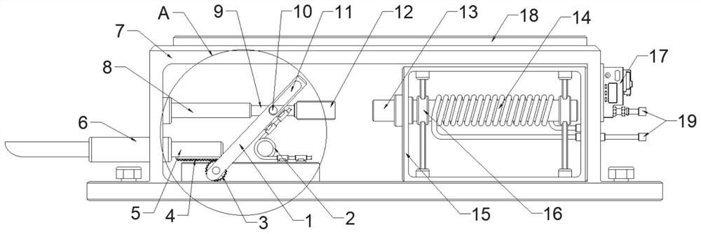
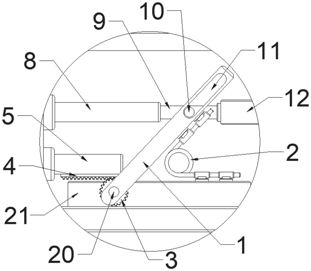
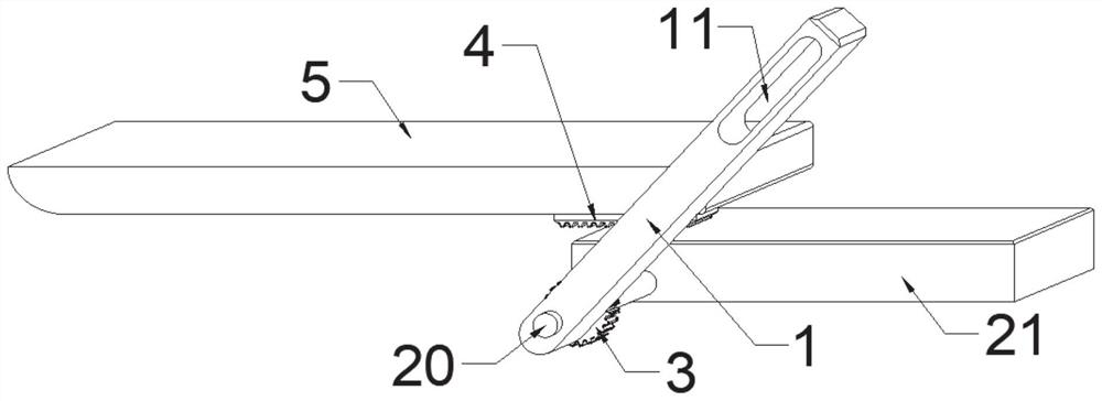
The invention discloses a mechanical positioning mechanism, a lockset and an electromagnetic locking system. The mechanical positioning mechanism comprises a swinging power assembly, wherein the swinging power assembly is arranged on the side edge of a protruding part, and the protruding part is fixed inside a mounting part, a positioning extension assembly is horizontally arranged on the mountingpart, and an engaging structure connects the positioning extension assembly with the swinging power assembly. Through identification of an access control card or a digital password, a conductor in anelectromagnetic attraction module is automatically connected to a power supply through an induction piece and generates a magnetic field, an adsorption part and a sliding part are attracted by an iron core to move, a driving part is driven to swing by means of a tabling part under the action of a mating groove, the driving part overcomes elastic force of the elastic part to drive a lock bolt to act by means of the engaging structure so as to realize a unlocking function, and the electromagnetic attraction assembly is automatically powered off after the electromagnetic attraction assembly is continuously electrified for a period of time under working of a timer, so that the lock bolt is automatically reset and locks under the elastic force of the elastic part, and the functions of smart positioning, unlocking and locking are achieved.

Description

technical field [0001] The invention relates to the field of positioning and locking, in particular to a mechanical positioning mechanism, a lock and an electromagnetic locking system. Background technique [0002] With the continuous deepening of my country's opening to the outside world, high-end buildings are developing rapidly, and the prospect of high-end locks market is optimistic. The investment in high-tech locks in my country's lock industry is increasing year by year, and the market demand for high-end locks is also increasing year by year. [0003] As the most widely used high-end door lock, it has an inductor inside. There is a coil in the inductor, which is always oscillating, which is equivalent to the primary coil of the transformer. There is also a coil in the card, which is equivalent to the secondary coil of the transformer. When the two coils are close to each other, the coupling generates current, which supplies power to the card, and at the same time co...

Claims


Application Information

Patent Timeline
IPC IPC(8): E05B49/00E05B15/10E05B15/00
CPCE05B15/00E05B15/101E05B49/00
Inventor 缪晓宾
Owner CHONGQING IND POLYTECHNIC COLLEGE
Learn More