Microbiological detection system
A technology of microbial detection and micro-channel structure, which is applied in the fields of enzymology/microbiology devices, biomass post-treatment, biomass pre-treatment, etc., can solve the problem of continuous phase fluid with large pressure difference, difficult to distinguish, and difference in filling effect of micro-reaction chamber etc. to achieve efficient droplet filling, eliminate background interference, and improve independence
- Summary
- Abstract
- Description
- Claims
- Application Information
AI Technical Summary
Problems solved by technology
Method used
Image
Examples
Embodiment 1
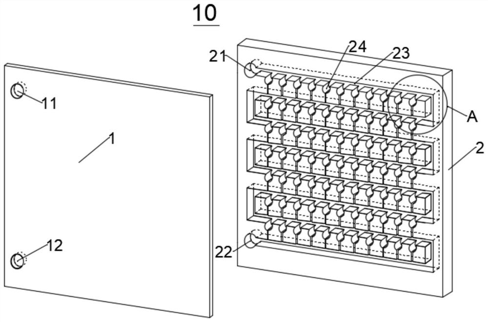
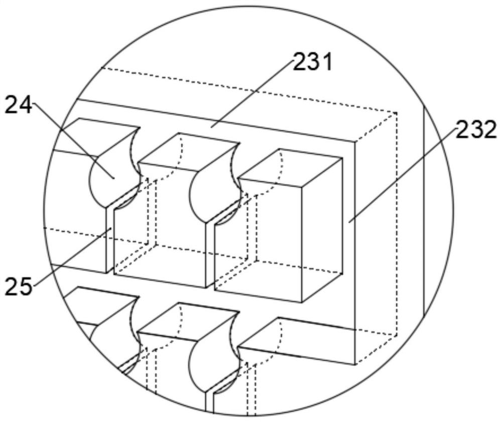
[0085] A method for preparing a vertical microbial detection chip is provided, the chip 10 only includes a double-layer structure of a cover layer 1 and a base layer 2, and the cover layer 1 is provided with an inlet through hole 11 and an outlet through hole 12; The substrate layer 2 is provided with a non-penetrating trough-like microchannel structure, the microchannel structure includes a sample inlet trough 21, a sample outlet trough 22, a delivery channel 23 bent and extended between the two, and connected to the delivery channel. The accommodating cavity 24 of the channel horizontal section and the side flow channel 25 connecting the bottom of the accommodating cavity 24 and the next horizontal section; the specific steps are as follows:
[0086] Step 1, select a cover sheet layer and a substrate layer with the same shape and size, wherein the material of the sheet layer can be conventional materials in the field, such as glass, PDMS, etc.;
[0087] Step 2, preparing a m...
Embodiment 2
[0102] Provide a kind of preparation method of vertical microbial detection chip, described chip 10 comprises cover sheet layer 1, base sheet layer 2 and and the structural layer 3 that is interposed between cover sheet layer 1 and base sheet layer 2, described cover The sheet layer 1 and the substrate layer 2 have an overlapping non-through microchannel structure; the cover sheet layer 1 has a through inlet through hole 11 and an outlet through hole 12; the base layer 2 has a corresponding non-through sample inlet Groove 21 and sample outlet groove 22; Described structural layer 3 comprises the part that overlaps with the microchannel structure on cover sheet layer 1 and substrate layer 2, and the sample feeding corresponding to described inlet through hole 11 and outlet through hole 12 The middle groove 31 and the middle groove 32 of the sample; only the microchannel structure of the structural layer 3 includes a middle layer side flow channel 35 for forming a lateral flow; t...
Embodiment 3
[0119] see Figure 11-19 , the chip 10 has eaves 242; specifically, it may be a double eaves 242 structure, or a single eaves 242 downstream of the accommodation chamber and a guide 243 upstream of the accommodation chamber, similar to the structure described above. Wherein, the eaves portion 242 and the guide portion 243 are both composed of the cover sheet layer 1 , the base sheet layer 2 and the structural layer 3 .
[0120] The sidewall of the middle layer delivery channel 33 has stronger hydrophilicity than the sidewalls of the water delivery channel on the cover sheet layer 1 and the substrate layer 2, so as to allow the middle layer side flow channel 35 to have a relatively small In the case of a cross-sectional area of 35, the same lateral flow intensity is provided, so that the induction effect on micro-droplets will not be reduced due to the reduction of the cross-sectional area of the side flow channel 35 in the middle layer.
PUM
 Abstract
Description
Claims
Application Information
 - R&D Engineer
- R&D Manager
- IP Professional
- Industry Leading Data Capabilities
- Powerful AI technology
- Patent DNA Extraction
Browse by: Latest US Patents, China's latest patents, Technical Efficacy Thesaurus, Application Domain, Technology Topic, Popular Technical Reports.
© 2024 PatSnap. All rights reserved.Legal|Privacy policy|Modern Slavery Act Transparency Statement|Sitemap|About US| Contact US: help@patsnap.com


