
Wafer conveying equipment, chemical mechanical planarization device and wafer conveying method

A technology of transmission equipment and a transmission method, which is applied in chemical mechanical planarization devices, wafer transmission equipment, and wafer transmission fields, and can solve problems such as low transmission efficiency, long wafer transmission time, and impact on wafer quality and yield. Achieve the effect of improving transmission efficiency, avoiding frequent movement, and improving yield

Active Publication Date: 2020-09-01
HANGZHOU ZHONGGUI ELECTRONICS TECH CO LTD
View PDF10 Cites 6 Cited by
  • Summary
  • Abstract
  • Description
  • Claims
  • Application Information

AI Technical Summary

Problems solved by technology

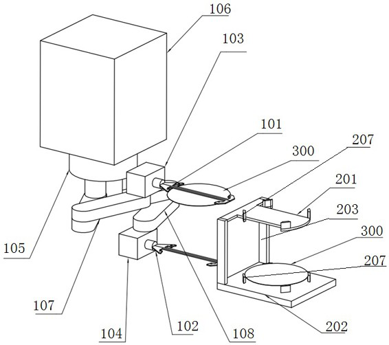
[0003] The existing wet environment manipulator can only carry one wafer at a time. The action of taking out the polished wafer and putting in the wafer to be polished needs to be completed in two steps. The wafer exchange mechanism can only place one wafer at a time, and cannot simultaneously Carry out the work of sending or taking the wafer in the polishing area; make the transfer time of the wafer longer and the transfer efficiency lower
And when the wafer passes through the polishing unit, the polishing liquid is attached to the surface of the wafer. If the time for transferring the wafer to the cleaning unit is too long, the polishing liquid will dry and adhere to the wafer, which will affect the quality and yield of the wafer.

Method used


Image

  • Wafer conveying equipment, chemical mechanical planarization device and wafer conveying method
  • Wafer conveying equipment, chemical mechanical planarization device and wafer conveying method
  • Wafer conveying equipment, chemical mechanical planarization device and wafer conveying method

Examples


Embodiment Construction

[0042]The following will clearly and completely describe the technical solutions in the embodiments of the present invention with reference to the accompanying drawings in the embodiments of the present invention. Obviously, the described embodiments are only some, not all, embodiments of the present invention. Based on the embodiments of the present invention, all other embodiments obtained by persons of ordinary skill in the art without making creative efforts belong to the protection scope of the present invention.

[0043] The core of the present invention is to provide a wafer transfer device. During the process of clamping and loosening the wafer, the first jaw corresponds to one of the first transfer table and the second transfer table, and the second jaw corresponds to the first transfer table. The transfer table corresponds to the other of the second transfer table, which can separate dry and wet, avoiding the polishing fluid and other liquids carried by the polished w...


PUM


Abstract

The invention discloses wafer conveying equipment, a chemical mechanical planarization device and a wafer conveying method. The wafer conveying equipment comprises a manipulator for clamping and carrying wafers and a transfer table for placing the wafers, wherein the manipulator comprises a first clamping claw, a second clamping claw, a lifting table, a moving mechanism, a rotating mechanism and acontrol mechanism, and the transfer table comprises a first transfer table body, a second transfer table body and a mounting frame. According to the wafer conveying equipment, the chemical mechanicalplanarization device and the wafer conveying method, in the conveying process, dry and wet separation can be achieved, liquid such as polishing liquid carried by polished wafers is prevented from polluting clean wafers, and the yield of the wafers can be increased; and besides, in the wafer conveying process, the first clamping claw and the second clamping claw can clamp or loosen the wafers at the same time, one clamping claw can clamp one wafer, and the other clamping claw can loosen another wafer at the same time, so that the process that a single clamping claw frequently moves is avoided,and the wafer conveying efficiency is improved.

Description

technical field [0001] The invention relates to the technical field of semiconductor integrated circuit chip manufacturing, and more specifically relates to a wafer transfer device. In addition, the present invention also relates to a chemical mechanical planarization device including the above-mentioned wafer transmission equipment and a wafer transmission method suitable for the above-mentioned wafer transmission equipment. Background technique [0002] CMP planarization equipment generally includes a semiconductor equipment front-end module (EFEM), a cleaning unit, and a polishing unit. In an existing chemical mechanical polishing and planarization device, the wafer transfer between the polishing area and other areas is realized through a wafer exchange mechanism and a manipulator. The wafer exchange mechanism mainly cooperates with the manipulator to complete the sending and receiving of wafers, and plays a bridge role between the peripheral equipment and the core part ...

Claims


Application Information

Patent Timeline
Patent Type & Authority Applications(China)
IPC IPC(8): B24B37/34B24B37/04B24B7/22B24B27/00H01L21/677H01L21/687
CPCB24B37/345B24B37/04B24B7/228B24B27/0023B24B27/0069H01L21/67742H01L21/68707H01L21/67766H01L21/67745H01L21/67173
Inventor 杨渊思周智鹏
Owner HANGZHOU ZHONGGUI ELECTRONICS TECH CO LTD
Learn More