
Distribution box door plate bevel edge process

A distribution box and door panel technology, which is applied in the field of the bevel edge process of the distribution box door panel, can solve the problems of reduced production efficiency, many punching and punching process steps, etc., and achieves the effect of improving quality

Active Publication Date: 2020-09-01
重庆博顺电气有限公司
View PDF6 Cites 0 Cited by
  • Summary
  • Abstract
  • Description
  • Claims
  • Application Information

AI Technical Summary

Problems solved by technology

[0004] The invention provides the beveling process of the door panel of the distribution box to solve the problems in the prior art that there are many steps in the stamping and punching process of the door panel and the production efficiency is reduced

Method used


Image

  • Distribution box door plate bevel edge process
  • Distribution box door plate bevel edge process
  • Distribution box door plate bevel edge process

Examples


Embodiment 1

[0037] Embodiment 1 is basically as attached figure 1 with figure 2 Shown:

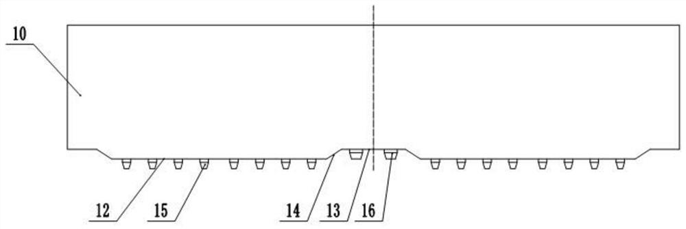
[0038] The beveled edge process of the door panel of the distribution box adopts a special mold for the beveled edge. The special mold includes an upper die head 10 and a lower die base 11. There are two punch faces at the bottom of the upper die head 10, and the two punch faces are opposite to the upper die head. The center line of the die head 10 is arranged symmetrically, wherein the convex die surface includes a raised edge 12 and side edges 13 arranged on both sides of the raised edge 12, the raised edge 12 and the side edge 13 are horizontally arranged, and the raised edge 12 and the side edge 13 are arranged horizontally. A hypotenuse 14 is formed between the sides 13, and the included angle between the hypotenuse 14 and the horizontal plane is not less than 30°, and in this application, the included angle is 33°.

[0039] On the raised edge 12, a plurality of hole punches 15 are fixed, and ...

Embodiment 2

[0049] Embodiment 2 is basically as attached Figure 4 Shown:

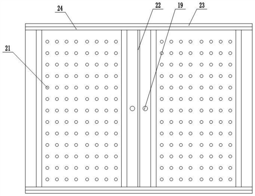
[0050] The difference from Embodiment 1 is that the load-bearing plate 20 is slidably connected in the first accommodation chamber 18, and a plurality of support frames 25 are fixed at the bottom of the first accommodation chamber 18, gaps are formed between adjacent support frames 25, and The width of the slit is greater than the aperture of the blanking hole 21, and a plurality of elastic members 26 are fixed between the load-bearing plate 20 and the support frame 25. When the load-bearing plate 20 is not stressed, its top surface exceeds the bottom surface of the die groove 17. In order to prevent The load-bearing plate 20 shakes, the load-bearing plate 20 is set as a rectangular plate, and a plurality of limit blocks 27 are fixed on the side 13 of the load-bearing plate 20, and the multiple limit blocks 27 are evenly distributed on the four sides of the load-bearing plate 20 13 , a plurality of vertical slots...


PUM


Abstract

The invention relates to the technical field of distribution box preparation, and particularly discloses a distribution box door plate bevel edge process. A special bevel edge mold is adopted and comprises an upper mold head and a lower mold base, convex mold faces are symmetrically arranged at the bottom of the upper mold head and comprise convex edges and side edges, bevel edges are formed between the convex edges and the side edges, a plurality of hole forming punches are evenly distributed on the convex edges, lock hole punches are arranged on the side edges, a concave mold groove is formed in the lower mold base, and a first containing cavity and a second containing cavity are formed in the bottom of the concave mold groove. The process comprises the specific steps that the upper moldhead is fixed to hydraulic equipment, and the lower mold base is fixed to a punch press; two door plates to be punched are placed on the lower mold base and are symmetrically placed relative to the center line of the upper mold head; and the upper mold head is driven to move downwards, and meanwhile punching of the two door plates are completed. By the adoption of the process, the door plate production efficiency is improved, and the service life of the mold is prolonged.

Description

technical field [0001] The invention relates to the technical field of distribution box preparation, in particular to a process for beveling the door panel of the distribution box. Background technique [0002] High-voltage distribution box refers to the electrical products used in power system power generation, transmission, distribution, power conversion and consumption to play on-off, control or protection, with a voltage level of 3.6kV ~ 550kV, mainly including high-voltage circuit breakers, high-voltage Disconnectors and grounding switches, high-voltage automatic reclosers and sectionalizers, and high-voltage switchgears. [0003] Since the electrical appliances in the distribution box will generate a certain amount of heat, it is necessary to open cooling holes on the box wall or door. It enters the inside of the box from the heat dissipation hole, which affects the work of the electrical appliance. Therefore, the usual practice is to glue the filter layer at the heat...

Claims


Application Information

Patent Timeline
IPC IPC(8): B21D28/34B21D28/26B21D37/10B08B15/04
CPCB21D28/34B21D28/26B21D37/10B08B15/04
Inventor 何鸿辉
Owner 重庆博顺电气有限公司
Learn More