


Quick Research
Generate reliable direction feasibility study reports for your R&D in just a few steps.

Technical Q&A
Discover and master advanced knowledge NOW. Basics, ideas, possibilities, all at once.

Find Solutions
As an expert in R&D theories, this can generate solutions to your technical problems instantly.

Evaluate Feasibility
Analyze your overall solution with one click, know your potential R&D risks in advance.

Monitor Landscape
Get weekly tech updates, stay abreast of the latest tech innovations and key insights.
Saving type air purifier for smart home
An air purifier and smart home technology, applied in chemical instruments and methods, dispersed particle separation, combined devices, etc., can solve problems such as filter element waste, and achieve the effects of improving purification effect, purification efficiency, and adsorption and filtration effect.
- Summary
- Abstract
- Description
- Claims
- Application Information
AI Technical Summary
Problems solved by technology
Method used
Image

Examples
Embodiment 1
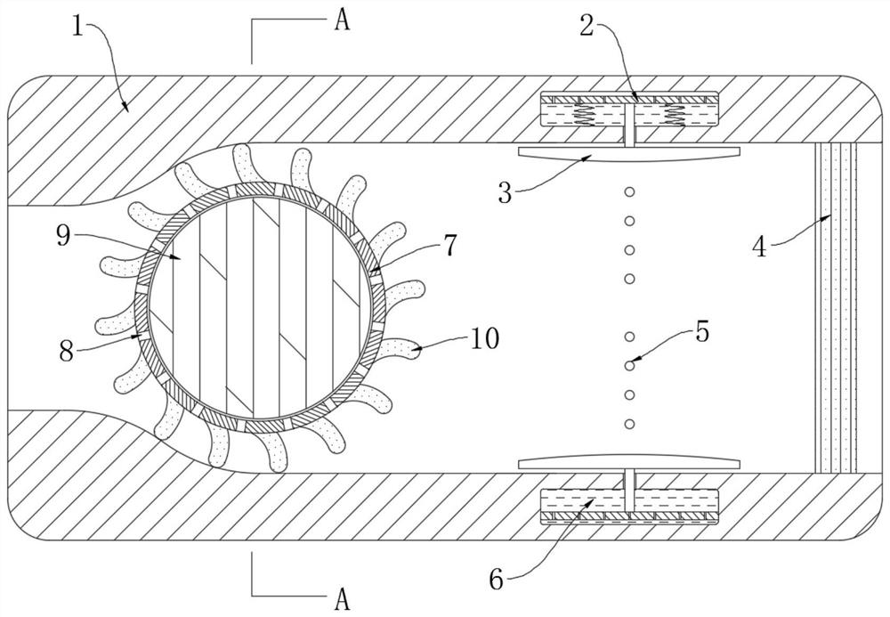
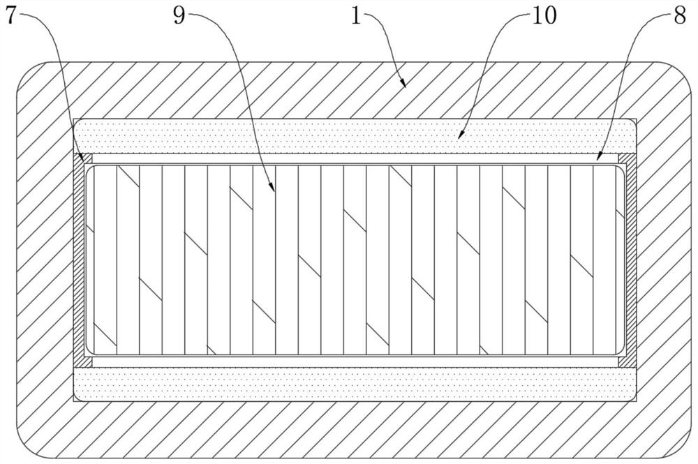
[0027] refer to Figure 1-4 , an energy-saving air purifier for smart home use, including a casing 1 with an air inlet and an air outlet, and a circulation filter mechanism, an atomization mechanism and a composite filter layer 4 are arranged in the casing 1 sequentially from left to right, and The composite filter layer 4 is close to the air inlet of the housing 1, and the composite filter layer 4 is integrated, including primary filter, medium filter, high efficiency filter, high efficiency activated carbon, etc.;
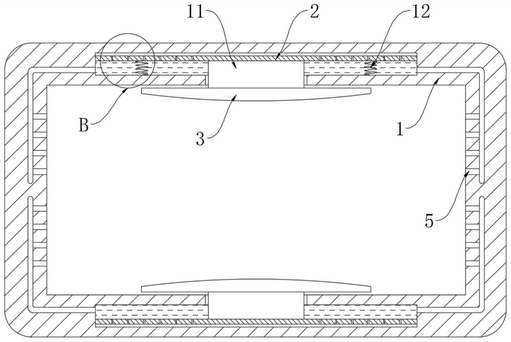
[0028] The atomization mechanism includes two liquid storage tanks 6 symmetrically arranged between the inner walls of the housing 1, each liquid storage tank 6 is sealed and slidably installed with a pressure plate 2, and each pressure plate 2 is provided with a plurality of convection holes 13, Each pressure plate 2 is fixedly connected with a wing plate 3 through a connecting plate 11, and each wing plate 3 is located in the housing 1 and is close to the inner...
Embodiment 2
[0039] refer to Figure 5-6 , the present embodiment differs from Embodiment 1 in that: wires 15 are horizontally arranged in each arc-shaped plate 10, and two permanent magnet plates 14 are symmetrically embedded on the housing 1, and between the two permanent magnet plates 14 It can be regarded as a uniform magnetic field, and the two permanent magnet plates 14 are symmetrical up and down with respect to the sleeve 7, and a filter 16 is installed in the casing 1, and the filter 16 is close to the air outlet.
[0040] In this embodiment, the filter element 16 includes a fixed ring 161 clamped in the housing 1 , and an elastic mesh layer 162 is laid on the fixed ring 161 . The elastic mesh layer 162 is woven with conductive threads.
[0041]When this embodiment is in use, when the airflow drives the sleeve 7 and the arc-shaped plate 10 to rotate counterclockwise, the wire 15 in the arc-shaped plate 10 continues to cut the magnetic induction line, so that an induced current app...
PUM
 Abstract
Description
Claims
Application Information
 - R&D Engineer
- R&D Manager
- IP Professional
- Industry Leading Data Capabilities
- Powerful AI technology
- Patent DNA Extraction
Browse by: Latest US Patents, China's latest patents, Technical Efficacy Thesaurus, Application Domain, Technology Topic, Popular Technical Reports.
© 2024 PatSnap. All rights reserved.Legal|Privacy policy|Modern Slavery Act Transparency Statement|Sitemap|About US| Contact US: help@patsnap.com