
Thyristor control series compensation control method for low-voltage power distribution network

A low-voltage distribution network and series compensation technology, applied in reactive power compensation, reactive power adjustment/elimination/compensation, electrical components, etc., can solve the problem that it is difficult to effectively control the low voltage of the distribution network and cannot directly apply LD-TCSC And other issues

Active Publication Date: 2020-08-28
CHONGQING UNIV
View PDF3 Cites 1 Cited by
  • Summary
  • Abstract
  • Description
  • Claims
  • Application Information

AI Technical Summary

Problems solved by technology

[0003] At present, many researches on the application of thyristor-controlled series compensation technology in high-voltage transmission network or medium-voltage distribution network have been carried out in China. However, in view of the particularity of LD-TCSC, the existing control methods and theories cannot be directly applied to LD-TCSC. It is mainly reflected in the following two aspects: 1) TCSC in medium and high voltage lines only considers the equivalent capacitive reactance or inductive reactance output, and the equivalent resistance and equivalent harmonic voltage accompanying the output are small and negligible compared with the line operating parameters , however, the resistance and harmonic voltage output of the LD-TCSC must be considered
2) Under the condition that the topological structure of the low-voltage distribution network is very complex, it is difficult for LD-TCSC to effectively control the low-voltage problem of the distribution network only by relying on the operating data near the installation node and the existing single-objective control method

Method used


Image

  • Thyristor control series compensation control method for low-voltage power distribution network
  • Thyristor control series compensation control method for low-voltage power distribution network
  • Thyristor control series compensation control method for low-voltage power distribution network

Examples


Embodiment Construction

[0069] Embodiments of the present invention are described below through specific examples, and those skilled in the art can easily understand other advantages and effects of the present invention from the content disclosed in this specification. The present invention can also be implemented or applied through other different specific implementation modes, and various modifications or changes can be made to the details in this specification based on different viewpoints and applications without departing from the spirit of the present invention. It should be noted that the diagrams provided in the following embodiments are only schematically illustrating the basic concept of the present invention, and the following embodiments and the features in the embodiments can be combined with each other in the case of no conflict.

[0070] Wherein, the accompanying drawings are for illustrative purposes only, and represent only schematic diagrams, rather than physical drawings, and should...


PUM


Abstract

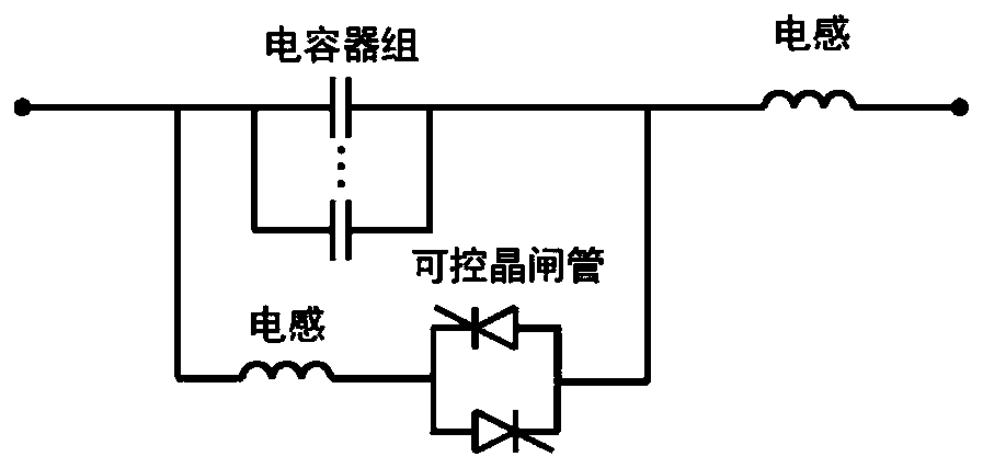
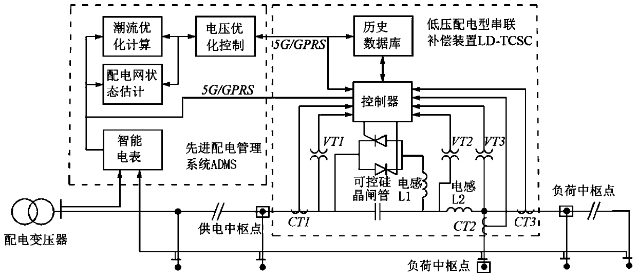
The invention relates to a thyristor control series compensation control method for a low-voltage power distribution network, and belongs to the field of power systems. The method comprises the following steps: S1, building an LD-TCSC topological structure; s2, taking a thyristor delay trigger angle as a main control variable, and constructing an equivalent mathematical model of LD-TCSC output capacitive reactance, resistance and harmonic voltage; s3, establishing a control optimization model by taking the minimum active power loss of the power grid as a target and taking power conservation, voltage reliability and the like as constraint conditions, solving the problems of voltage distribution and loss suppression of the power distribution network by utilizing the optimal power flow, and carrying out equipment output driving; and S4, establishing an on-line mode depending on the real-time data and an off-line mode depending on the historical data by utilizing the operation data near the installation node and taking whether the global operation data of the power grid can be effectively obtained as a criterion, and a control method of the on-line mode and off-line mode.

Description

technical field [0001] The invention belongs to the field of power systems, and relates to a thyristor-controlled series compensation control method for a low-voltage distribution network. Background technique [0002] The low-voltage power distribution network is located at the end of the system. Its grid structure is weak, the line is long, the line path is small, and the load increases rapidly, which often leads to serious voltage drop. In order to solve the low-voltage problem in the low-voltage distribution network, power system engineers usually use adjustment Transformer transformation ratio, strengthen network construction, increase power equipment and other measures. Installing uninterruptible power supply (UPS), static var compensator (SVC) and other power equipment is the most efficient, cheapest and most widely used means of voltage improvement. Frequent switching operations and other problems. In order to solve the problem of concentrated voltage improvement u...

Claims


Application Information

Patent Timeline
Patent Type & Authority Applications(China)
IPC IPC(8): H02J3/16H02J3/18
CPCH02J3/16H02J3/1807H02J2203/20Y02E40/10Y02E40/30
Inventor 张占龙赵晖端木子昂甘鹏飞肖睿
Owner CHONGQING UNIV
Learn More