
Two-point detection method and device based on wire magnetic field

A point detection and wire technology, applied in the field of two-point detection method and device based on wire magnetic field, can solve the problems of complicated installation, poor anti-interference ability, high cost, etc., and achieve the problems of complicated installation, convenient installation and strong anti-interference ability Effect

Pending Publication Date: 2020-08-28
ZHEJIANG WEISS WIRELESS NETWORK TECH CO LTD
View PDF5 Cites 0 Cited by
  • Summary
  • Abstract
  • Description
  • Claims
  • Application Information

AI Technical Summary

Problems solved by technology

[0017] The present invention provides a two-point detection method and device based on the magnetic field of the wire, which is used to overcome the shortcomings of the prior art such as complicated installation, high cost, poor anti-interference ability, and inability to comprehensively detect current and loose installation of the wire. at least one

Method used


Image

  • Two-point detection method and device based on wire magnetic field
  • Two-point detection method and device based on wire magnetic field
  • Two-point detection method and device based on wire magnetic field

Examples


Embodiment 1

[0042] Embodiment 1, an example of a two-point detection method based on the magnetic field of a wire

[0043] see figure 1 As shown, the embodiment of a two-point detection method based on the wire magnetic field provided by the present invention includes the following steps:

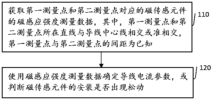
[0044] Step S110, obtaining the magnetic induction intensity measurement data of the magnetic sensing element corresponding to the first measurement point and the second measurement point, wherein, the straight line where the first measurement point and the second measurement point are located intersects or quasi-intersects the center line of the conductor, and the first measurement The distance between the point and the second measuring point is known;

[0045] Step S120, using the magnetic induction intensity measurement data to determine the current parameter of the wire, or determine whether the installation of the magnetic sensing element is loose.

[0046] In this embodiment, the intersection p...

Embodiment 2

[0127] Embodiment 2, an example of a two-point detection device based on the magnetic field of a wire

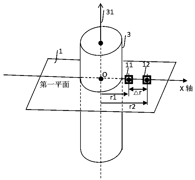
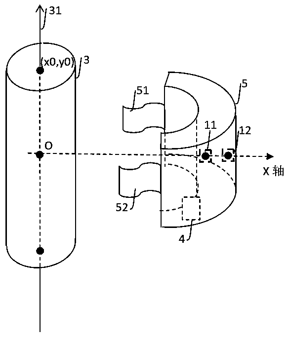
[0128] see Figure 2 to Figure 4 As shown, a two-point detection device based on the wire magnetic field includes:

[0129] perception module (7), processing module (4); wherein,

[0130] The perception module (7) is used to obtain the magnetic induction intensity measurement data of the magnetic sensing element corresponding to the first measurement point and the second measurement point. The distance between a measurement point and a second measurement point is known, including a magnetic sensing element (11) and a magnetic sensing element (12) corresponding to the first measuring point and the second measuring point;

[0131] The processing module (4) is used to use the magnetic induction intensity measurement data to determine the wire current parameters, or determine whether the installation of the magnetic sensing element is loose, including a signal conditioning mod...


PUM


Abstract

The invention provides a two-point detection method and device based on a wire magnetic field. The method comprises the steps of: obtaining magnetic induction intensity measurement data of magnetic sensing elements corresponding to a first measurement point and a second measurement point, wherein the straight line where the first measurement point and the second measurement point intersects or quasi-intersects with the center line of a wire, and the distance between the first measurement point and the second measurement point is known; and determining a wire current parameter by using the magnetic induction intensity measurement data, or judging whether the installation of the magnetic sensing element is loosened or not. Installation is convenient, an anti-interference capability is strong, and the device can be used for wire current detection and installation loosening detection.

Description

technical field [0001] The invention relates to the field of smart grids, in particular to a two-point detection method and device based on a wire magnetic field. Background technique [0002] Smart grid requires real-time detection of key electrical and environmental parameters to ensure efficient and reliable operation of the grid. The current detection of the transmission line is a basic content of the power grid detection. The vibration or galloping detection of the transmission line is also an important item to ensure the normal operation of the power grid. How to realize the The current detection of the transmission line, the vibration detection of the transmission line, and the economic and rapid deployment of the detection device are still a problem that needs further research. [0003] Using magnetic and electric fields to locate transmission lines, or to measure transmission line currents, is the basic technical approach adopted in the electric power field. From t...

Claims


Application Information

Patent Timeline
Patent Type & Authority Applications(China)
IPC IPC(8): G01R19/00G01R33/09G01V3/02
CPCG01R19/0092G01R33/09G01V3/02
Inventor 胡淼龙
Owner ZHEJIANG WEISS WIRELESS NETWORK TECH CO LTD
Learn More