Silencing device and compressor

A technology of a silencer and a compressor, which is applied in the field of compressors, can solve the problems of deterioration of compression performance, refrigerant gas entry, and high noise, and achieves the effects of reducing oil output, ensuring stability, and reducing noise.

Active Publication Date: 2020-08-28
ANHUI MEIZHI COMPRESSOR
View PDF8 Cites 0 Cited by
  • Summary
  • Abstract
  • Description
  • Claims
  • Application Information

AI Technical Summary

Problems solved by technology

Loud noise will affect the quality and reputation of the compressor; large oil discharge will affect the performance of the compressor, and may even cause "ice blockage"
In the related technology, the flow rate of the refrigerant gas that enters the muffler chamber from the inlet of the muffler will decrease during the release to the muffler space, and some refrigeration oil can be separated, but a large part of the refrigerant gas will still enter the compression chamber
However, the existing suction mufflers try to achieve miniaturization while maintaining the internal shape, so they cannot obtain sufficient muffler volume, and cannot attenuate the pulsation sound. The phenomenon that the agent gas is compressed, causing its compression performance to deteriorate

Method used


Image

  • Silencing device and compressor
  • Silencing device and compressor
  • Silencing device and compressor

Examples


Embodiment Construction

[0051] In order to understand the above-mentioned purpose, features and advantages of the present invention more clearly, the present invention will be further described in detail below in conjunction with the accompanying drawings and specific embodiments. It should be noted that, in the case of no conflict, the embodiments of the present application and the features in the embodiments can be combined with each other.

[0052] In the following description, many specific details are set forth in order to fully understand the present invention. However, the present invention can also be implemented in other ways different from those described here. Therefore, the protection scope of the present invention is not limited by the specific details disclosed below. EXAMPLE LIMITATIONS.

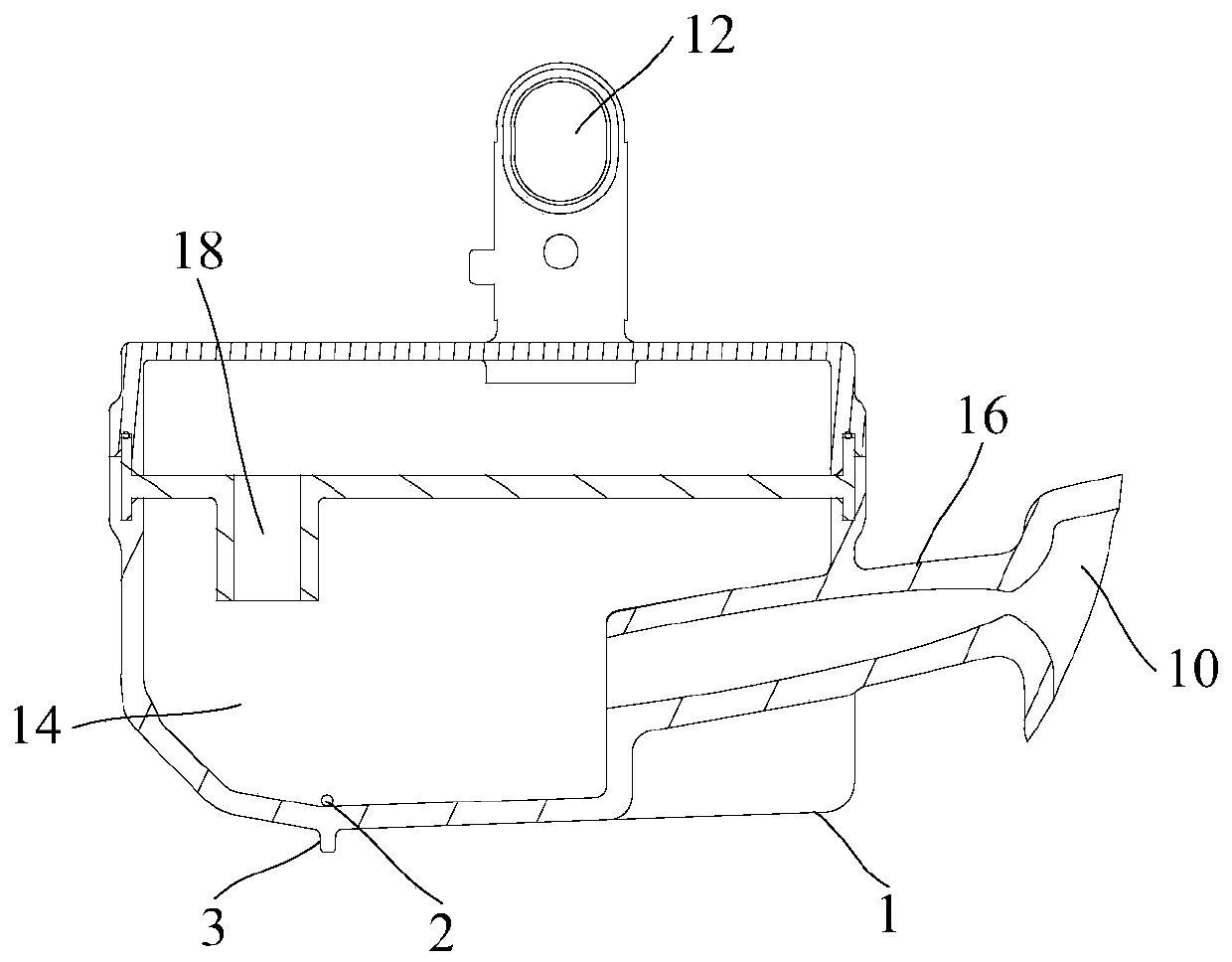
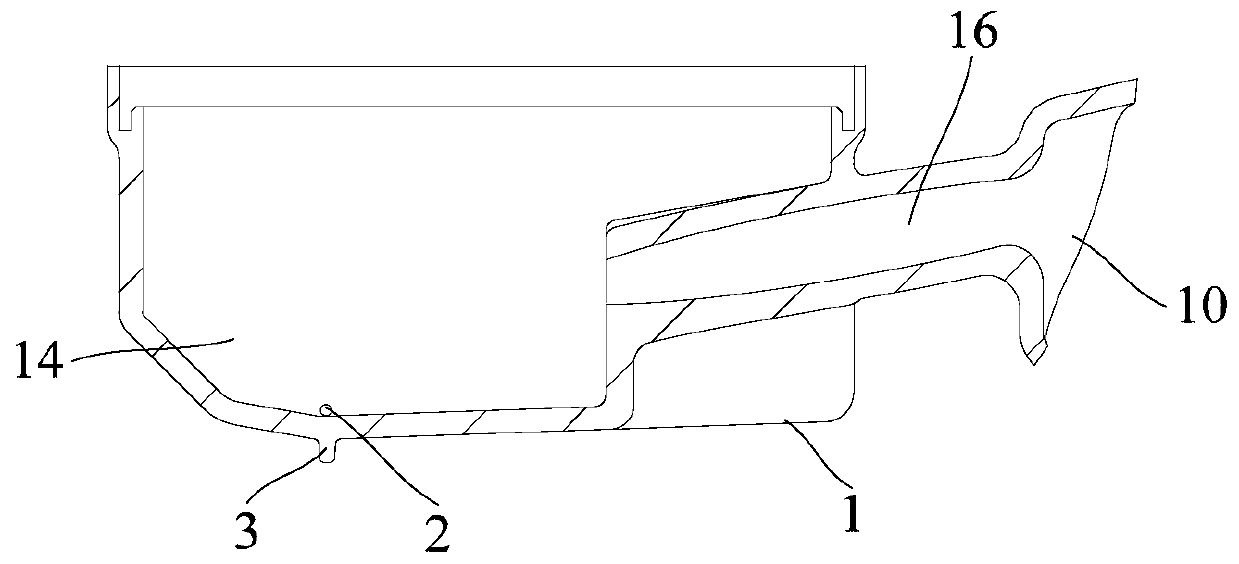
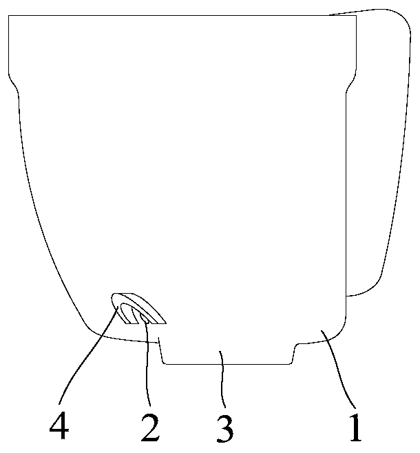
[0053] Refer below Figure 1 to Figure 7 A sound dampening device and a compressor according to some embodiments of the present invention are described.

[0054] According to an embodiment of the f...


PUM

PropertyMeasurementUnit
Diameteraaaaaaaaaa
Diameteraaaaaaaaaa
Draft angleaaaaaaaaaa

Abstract

The invention provides a silencing device and a compressor. The silencing device comprises a housing, an oil hole and an oil guide part, wherein the housing is provided with an air inlet and an air outlet, the housing is internally provided with an air flow channel, the air inlet and the air outlet communicate withe each other through the air flow channel, the oil hole is formed in the housing andused for allowing oil in the housing to be discharged, the oil guide part is arranged on the housing and located on the outer side of the housing, and the oil guide part is arranged below the oil hole in the oil dripping direction so that the oil can flow to the oil guide part from the oil hole and then drip. The provided silencing device comprises the housing, the oil hole formed in the housingand the oil guide part arranged on the housing, and the oil guide part is arranged on the outer side of the housing and located below the oil hole so that after the oil flows out of the oil hole, theoil can flow to the oil guide part, the oil guide part increases the surface adsorption force of the oil, the oil can be better gathered, when the gathered oil drops reach a certain gravity, the oil drops can be quickly dropped into the bottom of a housing of the compressor, the oil discharge amount of the compressor can be effectively reduced, the stability of internal oil circulation is ensured,and the noise of the compressor is also favorably reduced.

Description

technical field [0001] The present invention relates to the technical field of compressors, in particular to a noise reduction device and a compressor. Background technique [0002] At present, the miniaturization and high efficiency of compressors has become a trend, and it has also brought a series of problems, such as the reduction of suction efficiency, increased noise, and large oil discharge volume, etc., while performance, noise, and oil discharge volume have always been the key Important parameters for evaluating compressors. Loud noise will affect the quality and reputation of the compressor; large oil discharge will affect the performance of the compressor, and may even cause "ice blockage". In the related technology, the flow rate of the refrigerant gas that enters the muffler chamber from the inlet of the muffler will decrease during the release to the muffler space, and some refrigeration oil can be separated, but a large part of the refrigerant gas will still ...

Claims


Application Information

Patent Timeline
IPC IPC(8): F04B39/00F04B39/12
CPCF04B39/00F04B39/0083F04B39/12F04C29/02F04C29/06F04B53/04F04D29/665F04D29/706F04D29/403F04D29/063F04D29/66
Inventor 陈新杰黄刚
Owner ANHUI MEIZHI COMPRESSOR
Why Eureka
Try Eureka