Supporting platforms with adjustable dip angles and adjusting support
A technology for supporting platforms and adjusting brackets, which is applied in the directions of supporting frames, conveyor objects, transportation and packaging, etc., can solve the problems of wasting materials, long brackets, and increase costs, and achieve cost savings, convenient processing and installation, and height adjustment. Ability and angle adjustment capability for a wide range of effects
- Summary
- Abstract
- Description
- Claims
- Application Information
AI Technical Summary
Problems solved by technology
Method used
Image
Examples
Embodiment 1
[0038] Such as Figure 8 ~ Figure 10As shown, it is a support platform of the present invention, including a rotating body 11, a support frame 12 below the rotating body 11, and a connecting piece 13 connecting the supporting frame 12 of the rotating body 11; The second hole position 122 passed; the lower end of the rotating body 11 is provided with the first hole position 11a that allows the connecting piece 13 to pass through; the connecting piece 13 is a long rod and the end is sleeved with threads, and the end of the long rod is also sleeved Connected with a nut threadedly engaged with the long rod for locking, the rotating body 11 rotates around the support frame 12 due to the pivotal connection of the connecting piece 13 .
[0039] Such as Figure 8 As shown, the rotating body 11 includes a supporting rod 111 below, and the supporting rod 111 has a first hole 11a through which the connecting piece 13 passes. The upper surface of the rotating body 11 forms a supporting s...
Embodiment 2
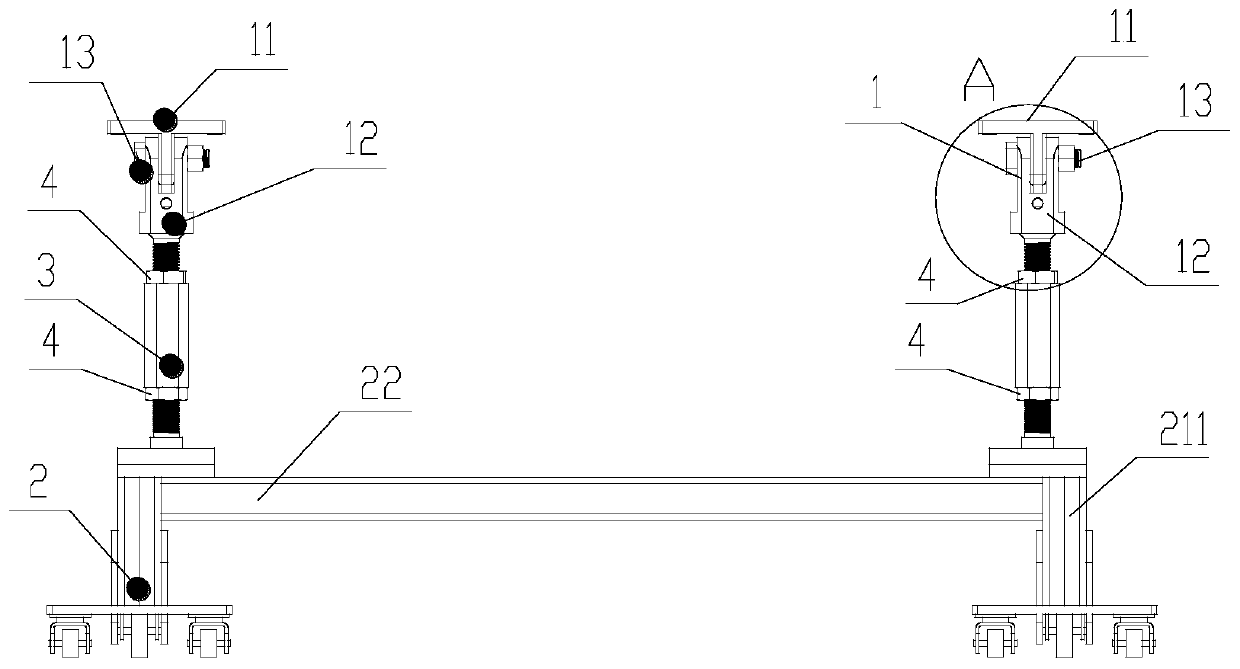
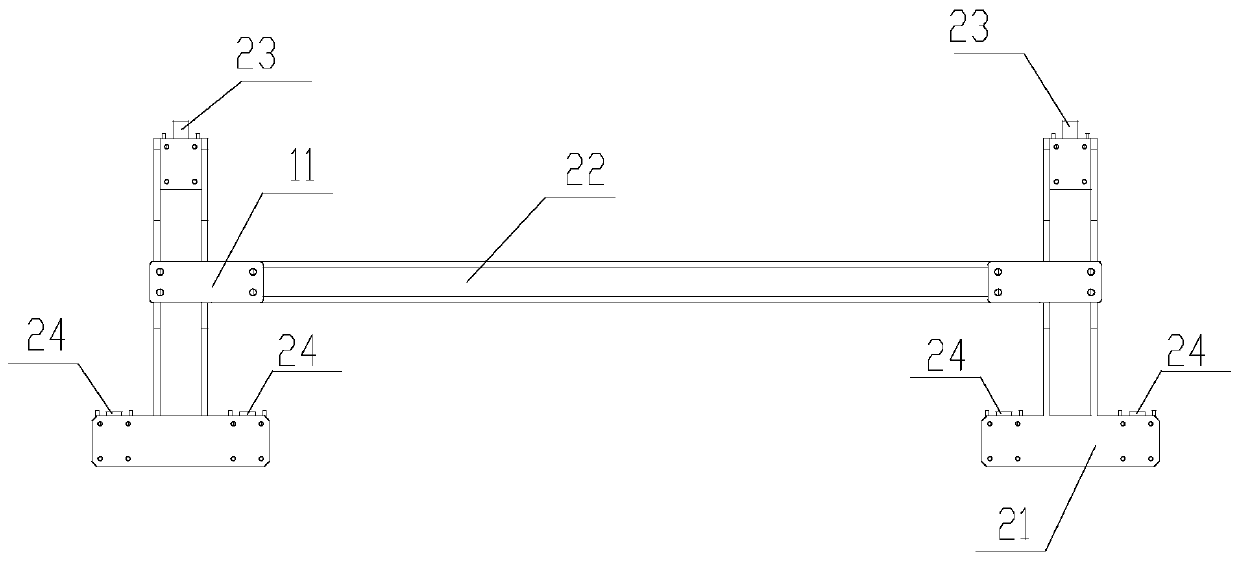
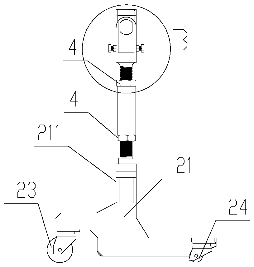
[0043] Such as Figure 1 to Figure 5 Shown is the adjustment bracket of the present invention, the adjustment bracket of the present invention includes the upper support platform 1 for placing materials with adjustable inclination angle and the carrying chassis 2 arranged below to make the support platform 1 walk and move, and the adjustment bracket also includes the same time with the lower part The carrying chassis 2 is connected and connected with the support platform 1 on the upper part, and the intermediate piece 3 which can adjust the height of the support platform 1 is connected. There are two supporting platforms 1 and two intermediate pieces 3, and the carrying chassis 2 is composed of two small chassis 21 and cross bars 22 fixedly connected to the two small chassis 21 respectively.
[0044] Such as Figure 1 ~ Figure 2 and Figure 4 ~ Figure 5 As shown, the lower part of the support frame 12 is a round bar or tube. In this embodiment, the lower part of the support ...
Embodiment 3
[0051] Such as figure 1 and image 3 As shown, the threads at the upper and lower ends of the middle piece 3 are respectively engaged with the threads on the outer surface of the lower part of the support frame 12 and the threads at the upper end of the protruding part 211 of the small chassis 21 .
[0052] Such as Figure 7 As shown, compared with Embodiment 2, the screw thread on the extension 211 on the small chassis 21 in this embodiment is just opposite to the screw thread on the extension 211 in Embodiment 1, so the middle piece in this embodiment The internal thread at the upper and lower ends of 3 is also opposite to the internal thread at the upper and lower ends of the middle piece 3 in Embodiment 1. Simultaneously, the rotation direction of the connector 13 in this embodiment is also opposite to that of the connector 13 in Embodiment 1,
[0053] Such as Figure 7 Shown are the position diagrams of the present invention in three different states. In the position ...
PUM
 Abstract
Description
Claims
Application Information
 - R&D
- Intellectual Property
- Life Sciences
- Materials
- Tech Scout
- Unparalleled Data Quality
- Higher Quality Content
- 60% Fewer Hallucinations
Browse by: Latest US Patents, China's latest patents, Technical Efficacy Thesaurus, Application Domain, Technology Topic, Popular Technical Reports.
© 2025 PatSnap. All rights reserved.Legal|Privacy policy|Modern Slavery Act Transparency Statement|Sitemap|About US| Contact US: help@patsnap.com


