A streamer crank pedal mechanism for shared bicycles
A technology for sharing bicycles and cranks, which is applied in crank structures, vehicle components, optical signals, etc., can solve the problems of poor warning effects of reflective sheets, and achieve enhanced warning effects, good warning effects, and smooth movement
- Summary
- Abstract
- Description
- Claims
- Application Information
AI Technical Summary
Problems solved by technology
Method used
Image
Examples
Embodiment 1
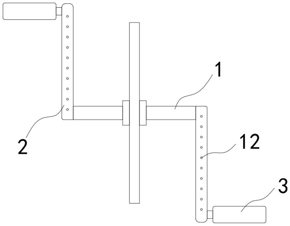
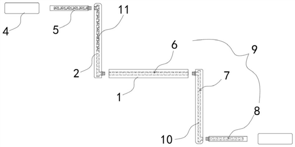
[0022] Such as Figure 1-2 As shown, a streamer crank pedal mechanism for shared bicycles includes a central axis 1, a crank 2 fixedly installed at both ends of the central axis 1, and a pedal 3 rotatably connected to the end of the crank 2. The pedal 3 includes a pedal body 4 and The fixed shaft 5, the fixed shaft 5 and the crank 2 are fixedly installed, the pedal body 4 is rotatably installed on the fixed shaft 5, the central shaft 1 is provided with a communication cavity 6, and the crank 2 is fixedly connected with a transparent connecting pipe 7, the fixed shaft 5 Made of transparent material, the fixed shaft 5 is provided with an accommodation chamber 8 , and the communication chamber 6 , the connecting pipe 7 and the accommodation chamber 8 communicate with each other to form a closed channel 9 .
[0023] The airtight channel 9 is filled with a flow liquid 10 and a fluorescent floating ball 11, the flow liquid 10 fills the entire airtight channel 9, the fluorescent floa...
Embodiment 2
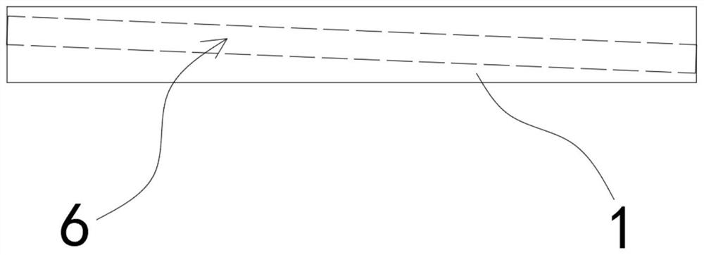
[0028] Such as image 3 As shown, the difference between this embodiment and Embodiment 1 is that the angle between the axis of the communication chamber 6 and the axis of the central axis 1 is 15°-30°, and when the axis of the communication chamber 6 is in a vertical plane , the two cranks 2 are in a vertical state, and the crank 2 on the upper side communicates with the upper end of the communication chamber 6 , and the crank 2 on the lower side communicates with the lower end of the communication chamber 6 .
[0029] In this embodiment, since the connecting chamber 6 is arranged obliquely, when the fluorescent floating ball 11 moves into the communicating chamber 6, it is not easy to gather, and it can move to a high place more smoothly, so that the moving track of the fluorescent floating ball 11 is smoother. coherent.
Embodiment 3
[0031] Such as Figure 4-5 As shown, the difference between this embodiment and Embodiment 1 is that: the three side walls of the pedal body 4 away from the crank 2 are fixedly connected with semi-cylindrical refraction strips 13, and the plane of the semi-cylindrical refraction strips 13 Connected with the side wall of the pedal body 4 , the axes of the three refraction strips 13 are distributed along the body of the pedal body 4 .
[0032] In this embodiment, since the refraction strip 13 is semi-cylindrical, it can be seen from the refraction of light that the light emitted from the fixed axis 5 will diverge around under the action of the refraction strip 13 (such as Figure 5 Shown on the left side of the center), increase the irradiation range of the light; the light received from the outside will be focused in the middle under the action of the refraction strip 13 (such as Figure 5 Shown on the right side in the middle), so that the fluorescent floating ball 11 in the ...
PUM
 Abstract
Description
Claims
Application Information
 - R&D Engineer
- R&D Manager
- IP Professional
- Industry Leading Data Capabilities
- Powerful AI technology
- Patent DNA Extraction
Browse by: Latest US Patents, China's latest patents, Technical Efficacy Thesaurus, Application Domain, Technology Topic, Popular Technical Reports.
© 2024 PatSnap. All rights reserved.Legal|Privacy policy|Modern Slavery Act Transparency Statement|Sitemap|About US| Contact US: help@patsnap.com


