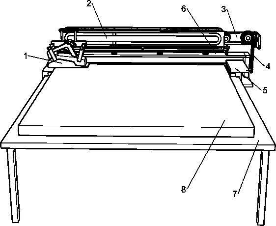
Wood board surface planing and polishing device
A planing and wood planing technology, applied in the field of planing and polishing devices for wood surfaces, can solve the problems of difficult planing and polishing with consistent strength, poor planing and polishing effect, low efficiency, etc., so as to prevent arm soreness and improve planing and polishing efficiency. , the effect of smooth forward movement
- Summary
- Abstract
- Description
- Claims
- Application Information
AI Technical Summary
Problems solved by technology
Method used
Image
Examples
Embodiment 1
[0026] A planing and polishing device for the surface of a plank, such as Figure 1-5 Shown, comprise bakelite planer 1, reciprocating mechanism 2, mounting frame 6, spring 61 and workbench 7, the rear portion of workbench 7 is slidingly connected with mounting frame 6, the top of mounting frame 6 evenly spaced connections A spring 61, a reciprocating mechanism 2 is connected between the tops of a plurality of springs 61, and a bakelite planer 1 is installed on the reciprocating parts of the reciprocating mechanism 2.
[0027] Reciprocating mechanism 2 comprises decelerating motor 21, fixed rod 22, guide frame 23, annular rack track 24, first gear 25, mounting plate 26, bearing frame 27 and limit plate 28, the bottom of mounting plate 26 and spring 61 The top is connected, the front side of the mounting plate 26 is connected with an annular rack track 24, and the front side of the top of the mounting plate 26 is connected with a load-bearing frame 27, the load-bearing frame 27...
Embodiment 2
[0030] On the basis of Example 1, such as figure 1 and Figure 6 As shown, it also includes a moving structure 5, the moving structure 5 includes a transmission shaft 51, a driving wheel 52, a first pulley 53 and a second pulley 54, the right side of the installation frame 6 is rotatably connected with a transmission shaft 51, and the transmission shaft 51 runs through the installation frame 6, and the left part of the transmission shaft 51 is connected with a driving wheel 52, which contacts the top of the workbench 7, and the top of the mounting frame 6 on the front and rear sides of the driving wheel 52 is evenly spaced in a rotary connection with multiple The first pulley 53, the inner top on the left side of the mounting frame 6 is also uniformly spaced and connected with a plurality of first pulleys 53 in rotation, the first pulley 53 contacts with the top of the workbench 7, and the inner bottoms on the left and right sides of the mounting frame 6 are all A plurality o...
Embodiment 3
[0033] On the basis of Example 2, such as Figure 6As shown, it also includes a telescopic transmission assembly 3 and a chain transmission assembly 4. The telescopic transmission assembly 3 includes a second gear 31, a first pulley 32, a second pulley 33, a flat belt 34, a bevel gear 35 and a second pulley. Three gears 36, the right side of the ring rack track 24 is rotationally connected with a first pulley 32, the front side of the first pulley 32 is connected with a second gear 31, the second gear 31 can mesh with the first gear 25, the first The front side of the mounting plate 26 on the right side of the pulley 32 is rotatably connected with a second pulley 33, a flat belt 34 is connected between the second pulley 33 and the first pulley 32, and the front side of the second pulley 33 is connected with a bevel gear 35. The right inner wall of the plate 26 is rotatably connected with a third gear 36, the third gear 36 meshes with the bevel gear 35, the chain transmission a...
PUM
 Abstract
Description
Claims
Application Information
 - Generate Ideas
- Intellectual Property
- Life Sciences
- Materials
- Tech Scout
- Unparalleled Data Quality
- Higher Quality Content
- 60% Fewer Hallucinations
Browse by: Latest US Patents, China's latest patents, Technical Efficacy Thesaurus, Application Domain, Technology Topic, Popular Technical Reports.
© 2025 PatSnap. All rights reserved.Legal|Privacy policy|Modern Slavery Act Transparency Statement|Sitemap|About US| Contact US: help@patsnap.com


