Film laminating machine for garlic planting
A laminating machine, garlic technology, applied in the application, plant protection, plant protection cover and other directions, can solve the problems of easy waist pain, affect work efficiency, difficult to get up, etc., to avoid waist pain, good effect, high work efficiency. Effect
- Summary
- Abstract
- Description
- Claims
- Application Information
AI Technical Summary
Problems solved by technology
Method used
Image
Examples
Embodiment 1
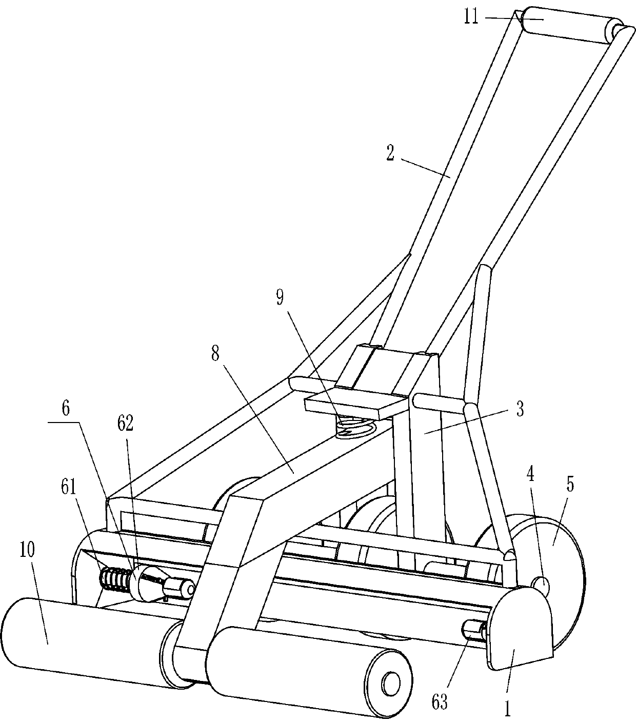
[0021] A film covering machine for garlic planting, such as Figure 1-2 As shown, it includes a frame body 1, a bracket 2, a special-shaped plate 3, a rotating shaft 4, a roller 5, and a limit mechanism 6. A bracket 2 is fixed in the middle of the outer top of the frame body 1, and the bracket 2 is arranged obliquely. A special-shaped plate 3 is fixedly connected between them, and a rotating shaft 4 is rotatably connected between the left and right sides of the bottom of the special-shaped plate 3. The middle part of the rotating shaft 4 and the left and right ends are fixedly connected with rollers 5. The limit mechanism 6 that the film is placed.
[0022] The limit mechanism 6 includes a movable rod 61, a first tapered frame 62, a second tapered frame 63 and a first spring 64, and the middle part of the right side of the frame body 1 is connected with the second tapered frame 63 in a rotating manner, and the frame The middle part of the left side of the body 1 is slidingly ...
Embodiment 2
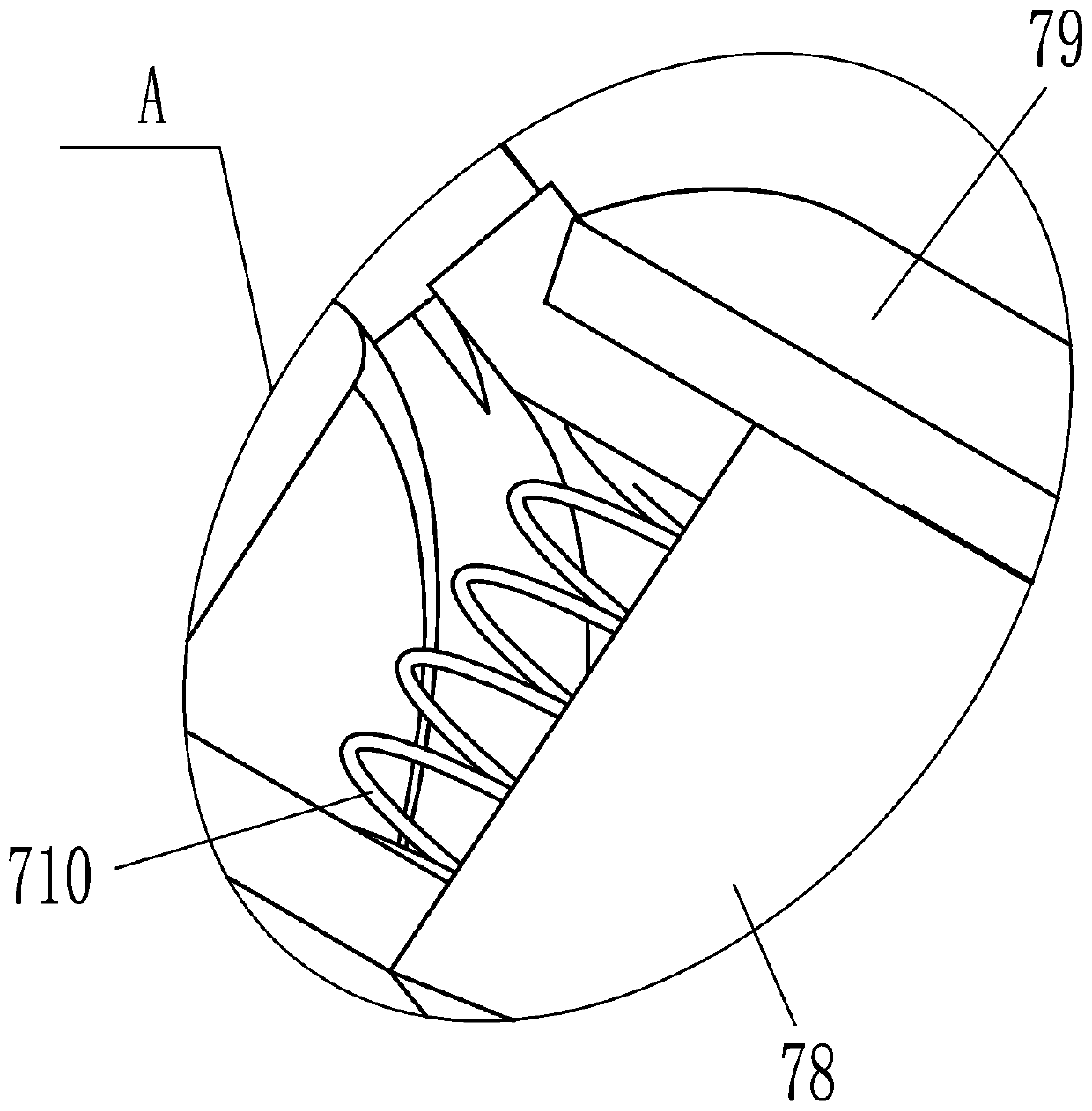
[0026] On the basis of Example 2, such as figure 2 and image 3 As shown, a clamping mechanism 7 is also included, and the clamping mechanism 7 includes a fixed rod 71, a sleeve 72, a contact wheel 73, a disc 74, a slide block 75, a clamping rod 76, a second spring 77, a wedge block 78, The arc-shaped plate 79 and the third spring 710, the right part of the first tapered frame 62 and the left part of the second tapered frame 63 are slidingly evenly spaced in the circumferential direction and are provided with a wedge block 78, and the outer surface of the wedge block 78 is fixedly connected with an arc. Shaped plate 79, arc-shaped plate 79 cooperates with the first tapered frame 62 and the second tapered frame 63, and the third spring 710 is connected between the outside of the left part of the left side wedge block 78 and the inner surface of the first tapered frame 62, The third spring 710 is also connected between the outside of the right side wedge block 78 right part an...
Embodiment 3
[0029] On the basis of embodiment 1 and embodiment 2, such as figure 1 As shown, it also includes an L-shaped bar 8, a fourth spring 9 and a pressure roller 10. An L-shaped bar 8 is hinged between the upper left and right sides of the special-shaped plate 3, and the left and right sides of the bottom end of the L-shaped bar 8 are all rotating. A pressure roller 10 is connected, and a fourth spring 9 is connected between the rear side of the outer top of the L-shaped bar 8 and the inner top of the special-shaped plate 3 .
[0030] It also includes a rubber sleeve 11, and the middle of the top of the bracket 2 is fixedly covered with a rubber sleeve 11.
[0031] When the operator pulls the device to move backward for lamination, the special-shaped plate 3 moves backward to drive the L-shaped rod 8 to move backward, and the L-shaped rod 8 moves backward to drive the pressure roller 10 to move backward, and the pressure roller 10 moves backward Contact with the film to compact it...
PUM
 Abstract
Description
Claims
Application Information
 - R&D
- Intellectual Property
- Life Sciences
- Materials
- Tech Scout
- Unparalleled Data Quality
- Higher Quality Content
- 60% Fewer Hallucinations
Browse by: Latest US Patents, China's latest patents, Technical Efficacy Thesaurus, Application Domain, Technology Topic, Popular Technical Reports.
© 2025 PatSnap. All rights reserved.Legal|Privacy policy|Modern Slavery Act Transparency Statement|Sitemap|About US| Contact US: help@patsnap.com


