
Energy-saving boiler tail gas purification system and method

A tail gas purification and energy-saving technology, which is applied in chemical instruments and methods, combustion methods, separation methods, etc., can solve the problems of difficult to effectively recover the heat of low-temperature flue gas, low-grade waste heat of medium-low temperature industrial tail gas, and limited heat extraction.

Pending Publication Date: 2020-08-28
新疆天富环保科技有限公司 +3
View PDF0 Cites 1 Cited by
  • Summary
  • Abstract
  • Description
  • Claims
  • Application Information

AI Technical Summary

Problems solved by technology

[0004] To sum up: it is of great significance to recover a large amount of medium and low temperature waste heat discharged from industrial tail gas, but the following problems exist in the existing technology: 1. Using the existing conventional heat exchange technology can only take out and utilize the heat above the acid dew point temperature of industrial tail gas , the heat taken out is limited; 2. Most of the heat of the industrial tail gas entering the industrial tail gas purification system is transferred to the washing liquid, the temperature of the tail gas drops sharply, and it is difficult to effectively recover the heat in the low-temperature flue gas and washing liquid; 3. The waste heat of the medium and low temperature industrial tail gas Low grade, difficult to reuse waste heat

Method used


Image

  • Energy-saving boiler tail gas purification system and method
  • Energy-saving boiler tail gas purification system and method
  • Energy-saving boiler tail gas purification system and method

Examples


Embodiment Construction

[0058] The following will clearly and completely describe the technical solutions in the embodiments of the application with reference to the drawings in the embodiments of the application. Apparently, the described embodiments are only some of the embodiments of the application, not all of them. Based on the embodiments in this application, all other embodiments obtained by persons of ordinary skill in the art without making creative efforts belong to the scope of protection of this application.

[0059] In order to better describe and illustrate the embodiments of the application, reference may be made to one or more drawings, but additional details or examples used to describe the drawings should not be regarded as an invention of the application, the presently described implementation limitations on the scope of any of the examples or preferred modes.

[0060] It should be noted that when a component is said to be "connected" to another component, it may be directly connec...


PUM

PropertyMeasurementUnit
Diameteraaaaaaaaaa
Lengthaaaaaaaaaa
Apertureaaaaaaaaaa

Abstract

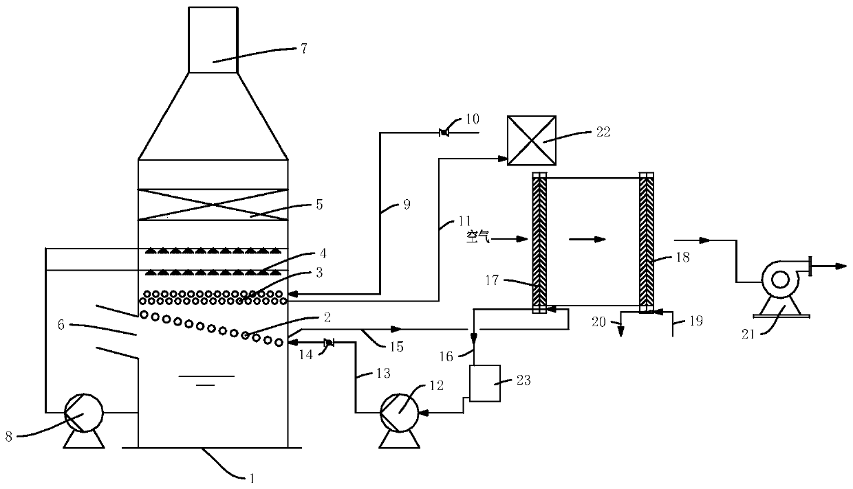
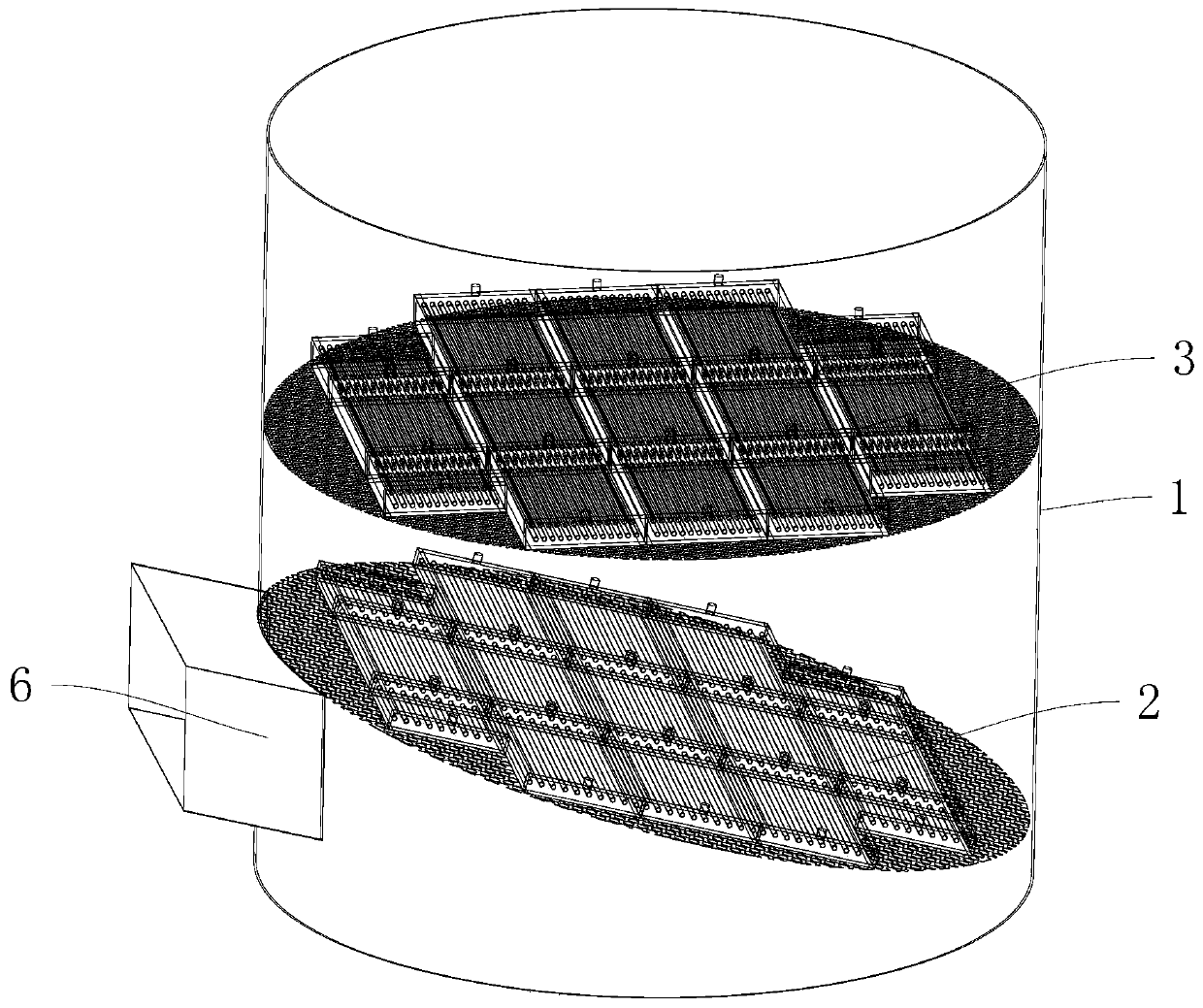
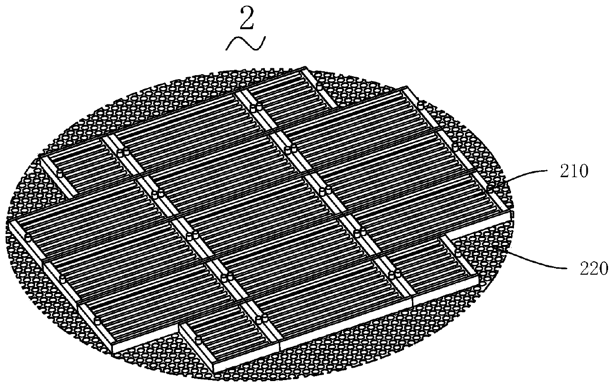
The invention discloses an energy-saving boiler tail gas purification system and method. The system comprises a washing tower, a washing pump, a pure water pipeline, an energy-saving pump, an energy-saving water pipeline, an air preheater, a steam pipeline and an air reheater; a flue gas inlet is formed in the side surface of the washing tower, a flue gas outlet is formed in the top of the washingtower, a flow equalizing layer, a venturi tube grid layer, a washing spraying layer and a demisting layer are sequentially arranged between the flue gas inlet and the flue gas outlet in the washing tower from bottom to top, and a washing liquid circulating pool is arranged below the flue gas inlet; the washing pump is used for communicating the washing liquid circulating pool with the washing spraying layer to form a circulating loop; the flow equalizing layer and the air preheater are connected into a circulation loop by the energy-saving pump; and the venturi tube grid layer is connected with a pure water pipeline. Low-grade waste heat in low-industrial tail gas can be effectively recycled, the recycled waste heat is used for boiler air preheating and boiler deaerator water supplementing, and boiler operation energy consumption is reduced.

Description

technical field [0001] This application relates to the technical field of new energy and energy saving, and in particular to an energy-saving tail gas purification system and method. Background technique [0002] About 50% of the heat in industrial production is directly discharged into the atmosphere as waste heat in various forms, which not only wastes energy, but also causes thermal pollution to the environment. Reasonable recovery of waste heat from medium and low temperature flue gas is of great significance to energy saving and consumption reduction of enterprises. Flue gas waste heat can be divided into low, medium and high temperature flue gas waste heat according to different temperatures. Among them, the temperature of low temperature flue gas waste heat resources is less than 100 ℃, the temperature of medium temperature flue gas waste heat resources is between 100-300 ℃, and high temperature The temperature of the flue gas waste heat resource is greater than 300°...

Claims


Application Information

Patent Timeline
IPC IPC(8): B01D53/78B01D53/80F23J15/06F23J15/04F23L15/00
CPCB01D53/343B01D53/78B01D53/80F23J15/06F23J15/04F23L15/00Y02E20/34
Inventor 杨志国李奇隽戚江平秦乐潘浩陈晓雨摆玉芬曲欣武承甲王力飞
Owner 新疆天富环保科技有限公司
Learn More