A cable head production platform
A technology for making platforms and cable heads, which is applied in the direction of equipment for connecting/terminating cables, etc. It can solve the problems of slow work efficiency, low degree of automation, and potential safety hazards, so as to prevent loosening, increase the bite force, and avoid processing quality. Effect
- Summary
- Abstract
- Description
- Claims
- Application Information
AI Technical Summary
Problems solved by technology
Method used
Image
Examples
Embodiment 1
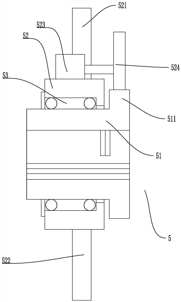
[0037] Embodiment 1, this embodiment discloses a cable head manufacturing platform, such as Figures 1 to 4As shown, it includes a frame 1 and a first fixing assembly 2 and a second fixing assembly 3 located on the left and right sides of the frame 1 respectively. The matching cutting assembly 5, the first fixing assembly 2 and the second fixing assembly 3 are respectively provided with a first fixing frame 21 and a second fixing frame 31, both of which are provided on the first fixing frame 21 and the second fixing frame 31 There is a cable locking device 22 adapted to the cutting assembly 5. The cutting assembly 5 includes an annular tool holder 51 and a fixing ring 52 sleeved outside the annular tool holder 51. The annular tool holder 51 is fixedly connected with the power cable 4. The ring-shaped blade holder 51 is arranged in a T-shaped structure, and a blade holder bearing 53 is provided at the connection between the ring-shaped blade holder 51 and the fixed ring 52, and...
Embodiment 2
[0044] Embodiment 2, this embodiment is based on Embodiment 1, such as Figure 5 As shown, the cable locking device 22 also includes a corresponding locking motor 225 and a locking ring 226. The main shaft of the locking motor 225 is fixedly connected with a first locking tooth 224 wheel. There is a second locking tooth 224 integral with it, and the second locking tooth 224 and the first locking tooth 224 are engaged with each other, and the inner side of the locking ring 226 is provided with the locking protrusion 222. The locking inner thread is adapted, and the outer surface of the locking protrusion 222 is provided with a locking outer thread that matches the locking inner thread; the locking motor 225 drives the second locking tooth through the first locking tooth 224. 224 rounds, thereby driving the locking ring 226 to rotate. The locking ring 226 automatically locks the power cable 4 passing through the locking sleeve 221 by cooperating with the locking protrusion 222 t...
Embodiment 3
[0047] Embodiment 3, on the basis of Embodiment 2, this embodiment is as follows: Image 6 As shown, one side of the fixed ring 52 is also provided with a suitable cutting device 9, and the cutting device 9 includes a corresponding lower blade 91, an upper blade 92 and a cutting electric cylinder 93. 91 and the cutting motor are fixedly connected to each other, and the piston rod of the cutting electric cylinder 93 and the upper blade 92 are fixedly connected to each other; The redundant power cable 4 is convenient for the production of the cable head.
[0048] To sum up, the present invention has the following beneficial effects:
[0049] 1. The two ends of the power cable 4 are locked and fixed by the cable locking device 22 on the first fixing frame 21 and the second fixing frame 31 to prevent the cable from loosening during the cutting process. The circular cutting blade cuts the skin of the power cable 4, and the adjusting motor 71 drives the adjusting screw 7 to rotate...
PUM
 Abstract
Description
Claims
Application Information
 - R&D Engineer
- R&D Manager
- IP Professional
- Industry Leading Data Capabilities
- Powerful AI technology
- Patent DNA Extraction
Browse by: Latest US Patents, China's latest patents, Technical Efficacy Thesaurus, Application Domain, Technology Topic, Popular Technical Reports.
© 2024 PatSnap. All rights reserved.Legal|Privacy policy|Modern Slavery Act Transparency Statement|Sitemap|About US| Contact US: help@patsnap.com


