
Biomass pyrolysis horizontal converter with bearable sealing structure

A biomass pyrolysis and sealing structure technology, which is applied in the field of biomass pyrolysis horizontal converters, can solve problems such as sealing problems, achieve fast wear speed, sufficient pyrolysis reaction, and facilitate purification and utilization

Active Publication Date: 2020-08-25
广州市博乐锅炉有限公司
View PDF23 Cites 0 Cited by
  • Summary
  • Abstract
  • Description
  • Claims
  • Application Information

AI Technical Summary

Problems solved by technology

[0002] Biomass pyrolysis is to convert biomass into combustible gas and natural resources. It has the advantages of high energy conversion rate, easy access to raw materials, easy transportation, and easy industrial utilization. At present, biomass pyrolysis technology has also gained more and more attention. There are many researches and developments. The existing biomass pyrolysis furnaces are mainly vertical and horizontal. Among them, the horizontal converter has gradually expanded its application range due to the characteristics of slow material movement, sufficient pyrolysis, and convenient product control. However, the current A horizontal converter is often equipped with a lot of rotating parts in the furnace body and needs to be equipped with a drying furnace, and because the whole cylinder is constantly rotating, the gap between the cylinder and the gas extraction parts or the head parts at both ends of the cylinder The sealing between them has become one of the difficult problems. For example, the patent document CN201014917Y discloses a fully sealed atmosphere-protected high-temperature continuous calcination rotary furnace, and the patent document CN201242334Y discloses a connecting part between the drum dryer and the hot blast stove, which essentially solves the Both are sealing issues between the rotating cylinder and the end connecting parts, and both of them use two seals in face-to-face contact, and use spring force to press the two seals together to achieve sealing

Method used


Image

  • Biomass pyrolysis horizontal converter with bearable sealing structure
  • Biomass pyrolysis horizontal converter with bearable sealing structure
  • Biomass pyrolysis horizontal converter with bearable sealing structure

Examples


Embodiment Construction

[0023] The present invention will be further described in detail below in conjunction with the accompanying drawings and embodiments.

[0024] The implementation method of the present invention is illustrated by specific specific examples below, and those skilled in the art can easily understand other advantages and effects of the present invention from the content disclosed in this specification.

[0025] Referring to the accompanying drawings, the structures, proportions, sizes, etc. shown in the accompanying drawings of this specification are only used to match the content disclosed in the specification, for those who are familiar with this technology to understand and read, and are not used to limit the scope of the present invention. Therefore, it has no technical substantive meaning, and any modification of structure, change of proportional relationship or adjustment of size shall still fall within the scope of The technical content disclosed in the present invention mus...


PUM


Abstract

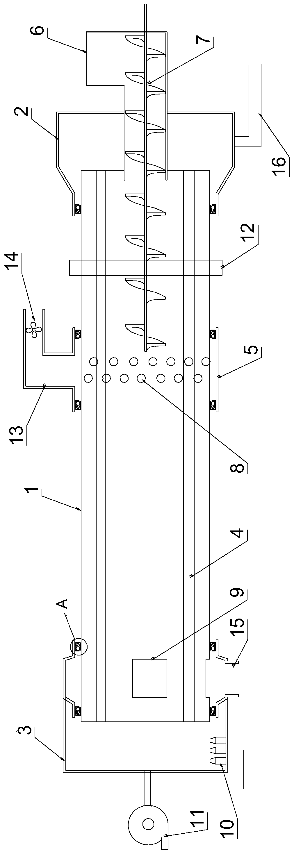
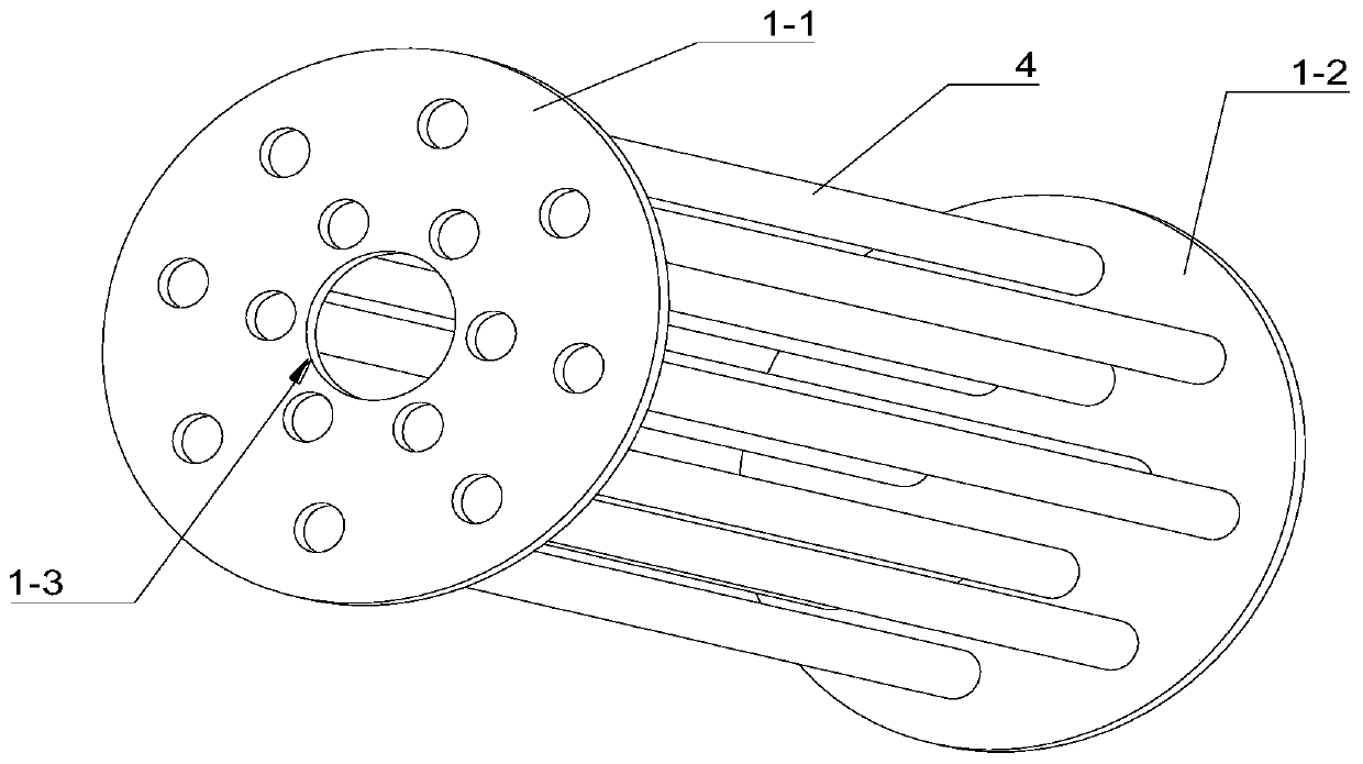
The invention aims to provide a biomass pyrolysis horizontal converter with a bearable sealing structure. According to the horizontal converter, pyrolysis and drying are completed in the same furnace;internal components of a converter barrel are simple and concise, the sealing performance between the horizontal converter and a static part is good; a bearing piece of a horizontal converter cylinder body does not need to be additionally arranged; installation, maintenance and replacement are simplified. The converter comprises a converter cylinder body, a front end socket arranged at the frontend of the converter cylinder body and a rear end socket arranged at the rear end of the converter cylinder body, wherein two ends of the cylinder body respectively extend into the front end socket and the rear end socket and are in relatively rotatable sealing connection with the front end socket and the rear end socket; a pyrolysis pipe for circulating heating gas is arranged in the cylinder body; the bottom of the front end socket is communicated with an exhaust pipe used for exhausting tail gas; a combustor is arranged at the bottom of the interior of the rear end socket; an air blower isfurther installed on the rear end socket, and the air blower is used for blowing heat energy generated by combustion of the combustor into the pyrolysis pipe.

Description

technical field [0001] The invention belongs to the technical field of biomass pyrolysis, and in particular relates to a biomass pyrolysis horizontal converter with a load-bearing sealing structure. Background technique [0002] Biomass pyrolysis is to convert biomass into combustible gas and natural resources. It has the advantages of high energy conversion rate, easy access to raw materials, easy transportation, and easy industrial utilization. At present, biomass pyrolysis technology has also gained more and more attention. There are many researches and developments. The existing biomass pyrolysis furnaces are mainly vertical and horizontal. Among them, the horizontal converter has gradually expanded its application range due to the characteristics of slow material movement, sufficient pyrolysis, and convenient control of products. However, the current A horizontal converter is often equipped with a lot of rotating parts in the furnace body and needs to be equipped with a...

Claims


Application Information

Patent Timeline
Patent Type & Authority Applications(China)
IPC IPC(8): C10B53/00C10B57/10
CPCC10B53/00C10B57/10
Inventor 焦彪彪
Owner 广州市博乐锅炉有限公司
Learn More