
A jet atomization flotation device

A jet atomization and equipment technology, applied in the field of jet atomization flotation equipment, can solve the problems of poor flotation effect, high energy consumption, low rotation speed, etc. balanced effect

Active Publication Date: 2021-05-25
ANHUI UNIV OF SCI & TECH
View PDF5 Cites 0 Cited by
  • Summary
  • Abstract
  • Description
  • Claims
  • Application Information

AI Technical Summary

Problems solved by technology

At present, jet flotation machines and mechanical agitation flotation machines are widely used in my country's mineral processing plants and coal preparation plants. Specifically, for example, in the flotation of fine coal, in the flotation stage, for Because the jet flotation machine is not equipped with a stirring device, when the concentration of the pulp is high, it cannot provide enough power to realize the full mixing and dispersion of the pulp, air bubbles, and flotation reagents; while the high speed of the stirring device of the mechanical stirring flotation machine The required energy consumption is relatively high, and the low rotational speed cannot form a good flow field and suction capacity; and in the prior art, the surfactant-foaming agent is basically directly put into the slurry for stirring. The active agent-foaming agent cannot be fully dispersed, and the microbubble system formed is unstable, and its effect cannot be better and more uniformly mixed with the flotation minerals, and the flotation effect is poor

Method used


Image

  • A jet atomization flotation device
  • A jet atomization flotation device
  • A jet atomization flotation device

Examples


Embodiment Construction

[0037] The technical solution in this embodiment will be clearly and completely described below in conjunction with the accompanying drawings in this embodiment. Obviously, the described embodiment is only a part of this embodiment, not the entire implementation. example. Based on the embodiments in this embodiment, all other embodiments obtained by persons of ordinary skill in the art without making creative efforts belong to the scope of protection of this embodiment.

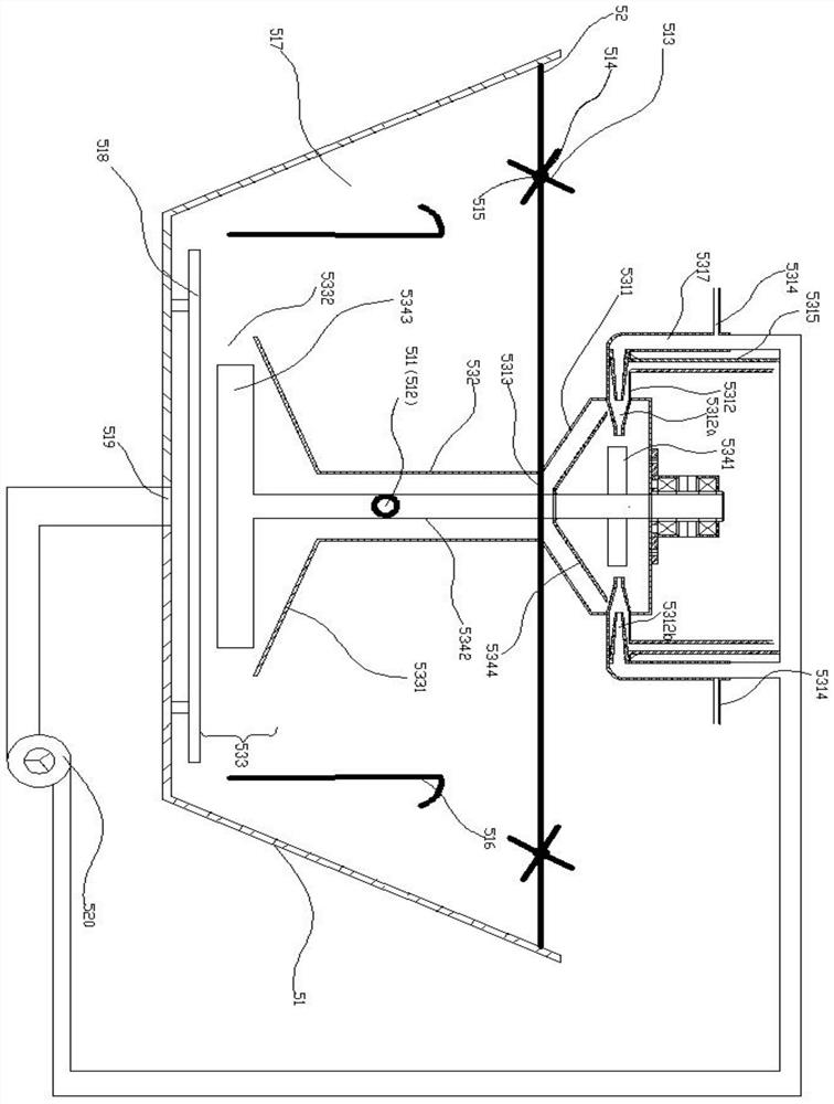
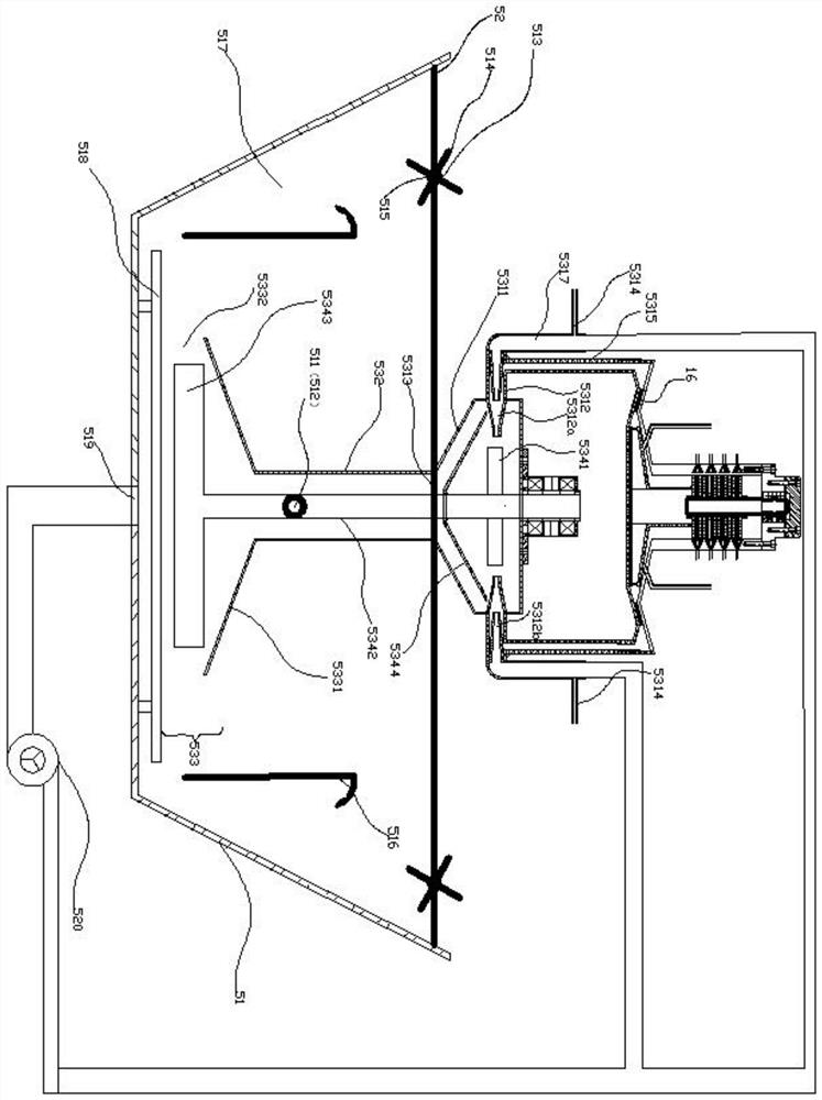
[0038] see figure 1 As shown, a double-wheel jet stirring mechanism includes a flotation cell 51, a support frame, a pretreatment bin 5311, a rotating connecting rod 5342, a driving impeller 5341, a stirring impeller 5343, a guide tube 532, a centrifugal stirring screen 5344 and a circulation pump 520,

[0039] The support frame (not shown in the figure) is installed at the opening of the upper end of the flotation cell 51, and the lower end of the pretreatment chamber 5311 is fixed with the support frame, ...


PUM


Abstract

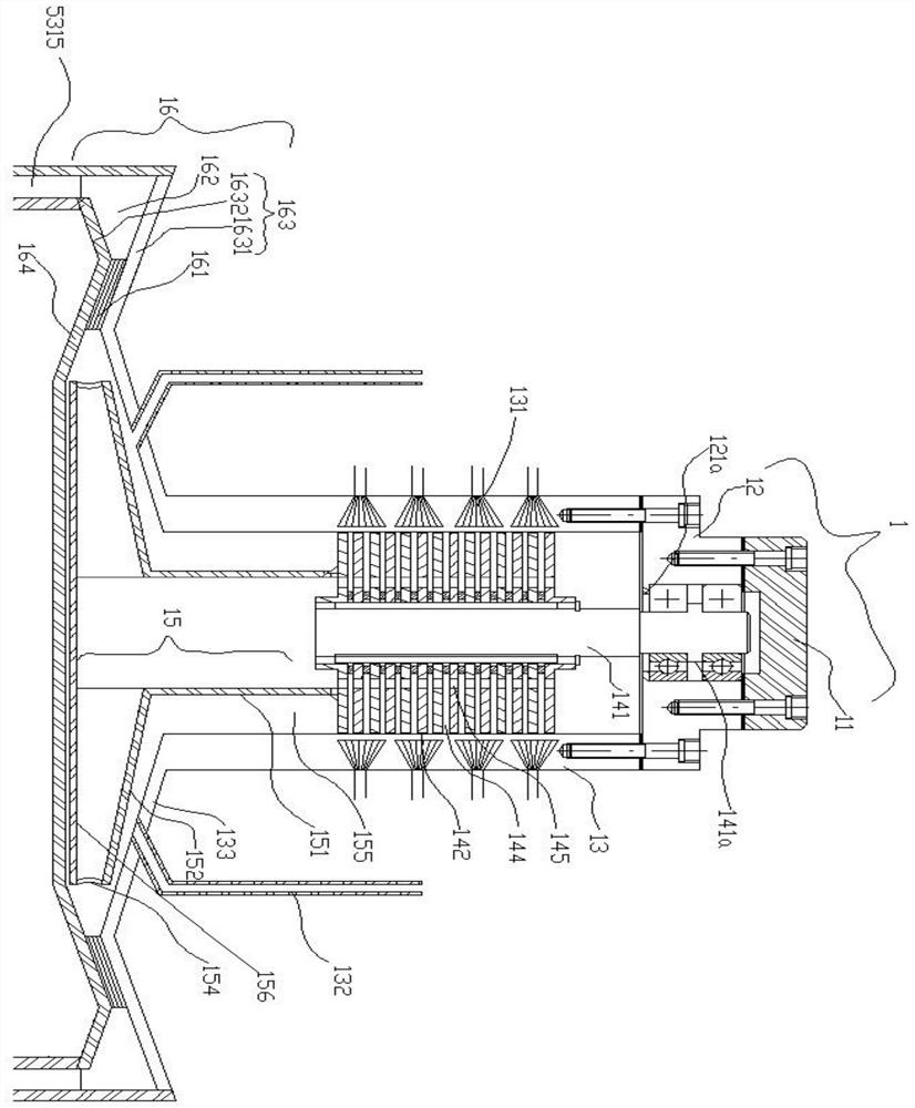
The invention discloses a jet atomization flotation device. The twin-wheel jet stirring mechanism includes a flotation tank, a support frame, a pretreatment bin, a rotating connecting rod, a driving impeller, a stirring impeller, a guide cylinder and a circulation pump; The atomization device includes an atomization cylinder, a rotating shaft, a laminar flow deflector, a conical deflector, an atomization turntable, and a secondary atomization shearing mechanism or a pressurized mixing and conveying mechanism; The jet energy injected by the empty jet nozzle realizes the effective utilization of energy, reduces energy consumption, and makes the collector react with the pulp in advance, changes the hydrophobicity of the mineral surface, and provides a good adsorption interface for efficient mineralization with air bubbles; at the same time The foaming agent is pre-atomized and then contacted with air, which can keep the broken bubbles in an atmosphere that inhibits mergers, maintain the stability of the microbubble system, and improve the flotation effect.

Description

technical field [0001] The invention relates to the technical field of mining machinery manufacturing, in particular to flotation equipment for separating ore particles, and more specifically to a jet atomization flotation equipment. Background technique [0002] Flotation, also known as foam flotation, is based on the differences in the surface properties of various minerals, and the process of separating minerals from the pulp with the help of the buoyancy of air bubbles; flotation machines are mainly used in the technical field of flotation of complex refractory minerals. The fields mainly include coal slime, quartz minerals, etc. At present, jet flotation machines and mechanical agitation flotation machines are widely used in my country's mineral processing plants and coal preparation plants. Specifically, in the flotation of fine coal, in the flotation stage, for the commonly used Because the jet flotation machine is not equipped with a stirring device, when the concent...

Claims


Application Information

Patent Timeline
Patent Type & Authority Patents(China)
IPC IPC(8): B03D1/16B03D1/14B05B3/10B01F3/08B01F5/02B01F7/26B01F9/18B01F13/10B01F27/93B01F29/86
CPCB03D1/16B03D1/1418B03D1/1443B03D1/1456B03D1/145B03D1/1468B03D1/1475B05B3/1014B01F23/41B01F25/20B01F27/93B01F29/86B01F33/821B05B7/2486B05B7/2489B05B14/00B05B15/25B05B3/082B05B7/0408B03D1/14B03D1/1412B03D1/1462B03D1/1493B03D1/24B03D1/247B05B3/0418B05B3/1035
Inventor 王超朱金波周伟朱宏政董岩昊
Owner ANHUI UNIV OF SCI & TECH
Learn More