Breathable and environment-friendly mask supporting frame and sterilization mask applying same

A support frame and mask technology, which is applied in applications, clothing, clothing, etc., can solve the problems of hot air flow that cannot be eliminated in time, use comfort, reduced protective performance of masks, and poor face fitting comfort, etc., to achieve stable and firm structure. Simple, lightweight effect

Pending Publication Date: 2020-08-21
ZHONG HONG NANO FIBER TECH DANYANG
View PDF0 Cites 1 Cited by
  • Summary
  • Abstract
  • Description
  • Claims
  • Application Information

AI Technical Summary

Problems solved by technology

However, due to its own characteristics, the metal strip on the bridge of the nose can completely fit the nose. When wearing the mask for a long time or communicating, it is still easy to produce gaps, which will reduce the protective performance of the mask.
(2) The top edge of the mask fits on the face, resulting in poor breathing in the respiratory tract, resulting in a stuffy feeling on the face. The hot air in the mask cannot be removed in time, which affects the comfort of the human body. The mask structure in the form of a ventilation valve is used, and the cost of use is relatively high. high
(3) Part of the mask structure is equipped with a support frame structure, so that the mask has good shape support, but the fit and comfort of the face are poor

Method used


Image

  • Breathable and environment-friendly mask supporting frame and sterilization mask applying same
  • Breathable and environment-friendly mask supporting frame and sterilization mask applying same
  • Breathable and environment-friendly mask supporting frame and sterilization mask applying same

Examples


Embodiment Construction

[0044] In order to make the technical solution of the present invention clearer, the present invention will be further described below in conjunction with the accompanying drawings. Any solution obtained by equivalent replacement and conventional reasoning of the technical features of the technical solution of the present invention falls within the protection scope of the present invention. The fixed connection, fixed arrangement, and fixed structure mentioned in this embodiment are all known technologies known to those skilled in the art, such as thermal fusion welding, integral injection molding, and the like.

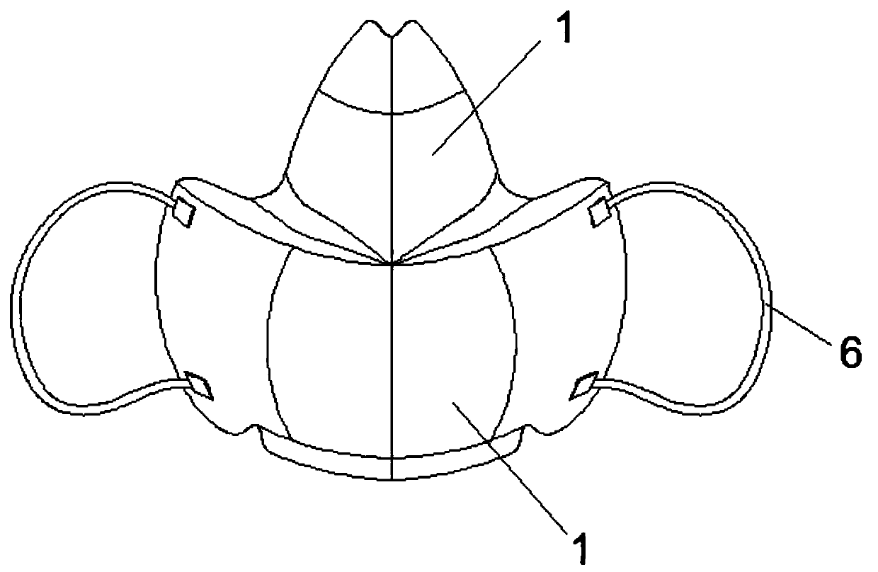
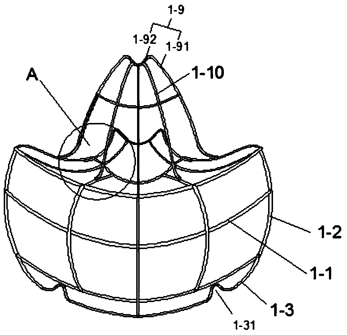
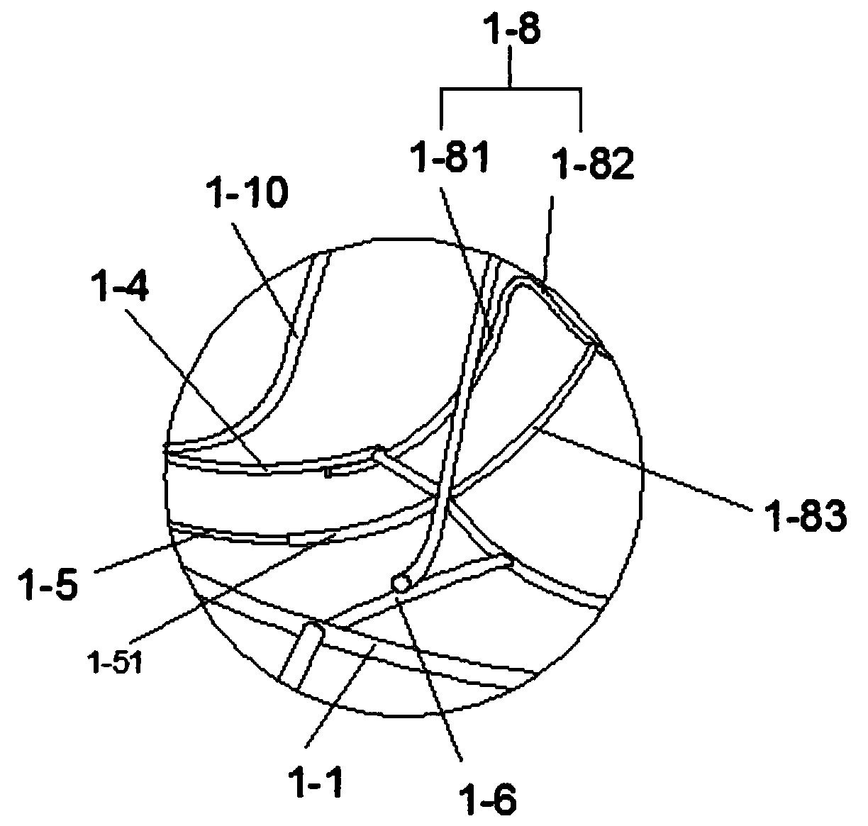
[0045] As can be seen in conjunction with the accompanying drawings, a breathable, environmentally friendly mask support frame, the support frame 1 includes a front face cross bar 1-1, a front face longitudinal bar 1-2, a front face bottom bar 1-3, a first ejector bar 1-4, The second push rod 1-5, the third push rod 1-6, the top connecting rod 1-7, the lower nose brid...


PUM


Abstract

A breathable and environment-friendly mask supporting frame comprises a front face transverse rod, a front face longitudinal rod, a front face bottom rod, a first ejector rod, a second ejector rod, athird ejector rod, a top connecting rod, a lower nose bridge rod, an upper nose bridge rod and an inclined supporting rod. A sterilization mask with the breathable and environment-friendly mask supporting frame comprises a supporting frame, a first non-woven fabric layer, filter paper, a second non-woven fabric layer, a third non-woven fabric layer, tying belts, an inner non-woven fabric layer, inner filter paper and a face attaching layer. The first non-woven fabric layer, the filter paper and the second non-woven fabric layer are sequentially arranged on the outer side of the supporting frame in a wrapping mode and are arranged in a layered mode. The third non-woven fabric layer is arranged on the inner side of the supporting frame in an attached mode. The tying belts are fixed to the two sides of the first non-woven fabric layer through hot melting. The inner filter paper is arranged on one side of the lower nose bridge rod, and the inner non-woven fabric layer is arranged on the two sides of the inner filter paper in an attached mode and wraps the lower nose bridge rod. The sterilization mask is high in breathability, comfortable to use and high in practicability.

Description

technical field [0001] The invention relates to the field of medical protection, in particular to a breathable, environment-friendly mask support frame and a sterilized mask applied thereto. Background technique [0002] The classification of masks includes medical protective masks (executive standard GB19083), disposable medical surgical masks (YY0469) and disposable medical masks (YY / T0969). Sterilized masks, like non-sterilized masks, need to be at the level of 100,000 Production in a dust-free workshop requires the same production indicators such as filtration efficiency or airflow resistance. Compared with ordinary non-sterile masks, an additional sterilization process is required for the finished product. At present, the sterilization of medical masks is sterilized by ethylene oxide EO. Since ethylene oxide is flammable, explosive and carcinogenic, it is also a respiratory protection product. It must be 7-14 days after EO sterilization. Analyzer until the residual eth...

Claims


Application Information

Patent Timeline
IPC IPC(8): A41D13/11A41D27/00A41D27/28
CPCA41D13/1115A41D13/1161A41D27/28A41D27/00
Inventor 崔建中
Owner ZHONG HONG NANO FIBER TECH DANYANG
Why Eureka
Try Eureka