An auxiliary transmission brake arrangement

A technology for transmission brakes and transmissions, used in medium and heavy vehicles, to control this auxiliary transmission brake device, light-duty field, can solve problems such as expensive, unfavorable response time, and achieve the effect of improving energy consumption and preventing excess lubrication

Active Publication Date: 2020-08-18
VOLVO LASTVAGNAR AB
View PDF5 Cites 0 Cited by
  • Summary
  • Abstract
  • Description
  • Claims
  • Application Information

AI Technical Summary

Problems solved by technology

[0007] However, this solution is quite expensive, and its response time is disadvantageous
Also, if the engagement of the clutch fails, the auxiliary transmission brake will have no braking effect

Method used


Image

  • An auxiliary transmission brake arrangement
  • An auxiliary transmission brake arrangement
  • An auxiliary transmission brake arrangement

Examples


Embodiment Construction

[0050] The present invention will now be described more fully hereinafter with reference to the accompanying drawings, in which exemplary embodiments of the invention are shown. However, this invention may be embodied in many different forms and should not be construed as limited to the embodiments set forth herein; rather, these embodiments are provided for sufficiency and completeness. Throughout the specification, the same reference numerals denote the same elements.

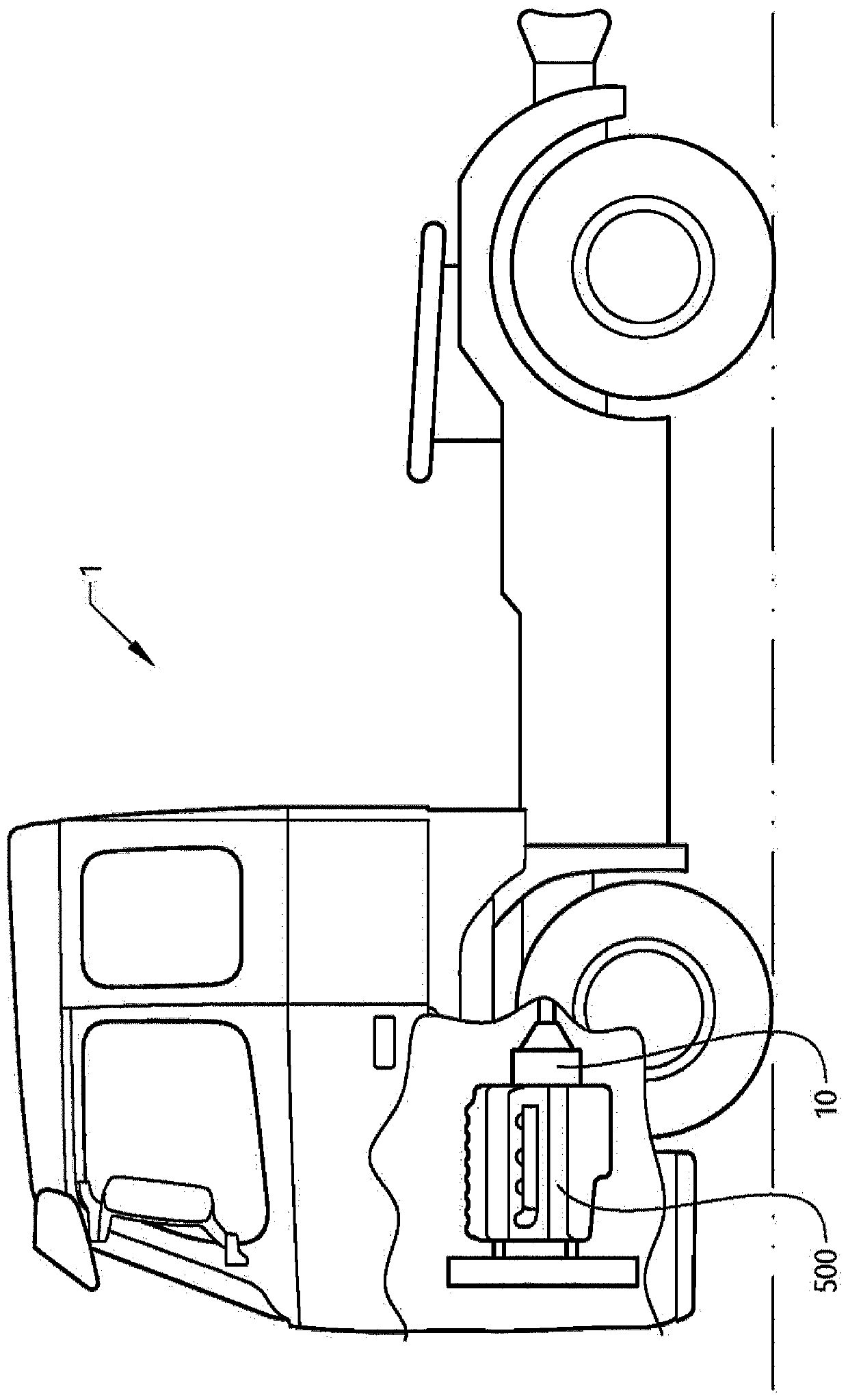
[0051] special reference figure 1 , a vehicle 1 in the form of a truck is provided. The vehicle 1 includes a prime mover 500 in the form of an internal combustion engine arrangement 500 , and a transmission 10 connected to the prime mover 500 . figure 1 Vehicle 1 in is particularly well suited to take advantage of the following Figure 2 to Figure 3 The description of the transmission 10 is described.

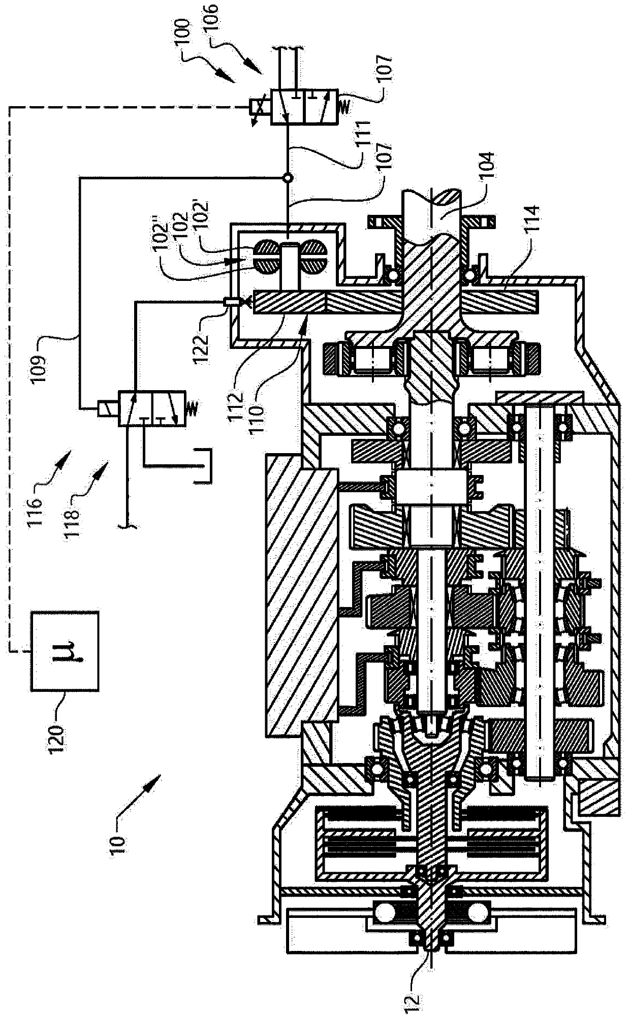
[0052] refer to figure 2 , figure 2 is a cutaway side view of the auxiliary transmission brake devi...


PUM


Abstract

The present invention relates to an auxiliary transmission brake arrangement (100) for a transmission (10) of a vehicle. In particular, the invention relates to an auxiliary transmission brake arrangement comprising a lubrication arrangement for improved lubrication of gear wheels connecting the auxiliary transmission brake arrangement to an output shaft.

Description

technical field [0001] The invention relates to an auxiliary transmission brake device for a transmission of a vehicle. The invention also relates to a corresponding method for controlling such an auxiliary transmission brake arrangement. The invention is applicable to vehicles, particularly light, medium and heavy duty vehicles commonly referred to as trucks. Although the invention will be described primarily in relation to trucks, the invention is also applicable to other types of vehicles. Background technique [0002] On light, medium and heavy duty vehicles, also commonly referred to as trucks, a transmission unit is connected to the prime mover to control the torque load from the prime mover to the propulsion wheels of the truck. Thereby, various ratios between the input shaft and the output shaft of the transmission device can be obtained. [0003] The transmission arrangement may also include an auxiliary transmission brake, also commonly referred to as a retarder...

Claims


Application Information

Patent Timeline
IPC IPC(8): F16H61/00B60T8/32B60T13/58F16H57/04
CPCB60T1/087B60T8/3215B60T10/02F16H61/0059F16D57/04F16H57/0446F16H57/0456F16H2061/0037F16H57/0435
Inventor 安德斯·海德曼
Owner VOLVO LASTVAGNAR AB
Why Eureka
Try Eureka