Transformer winding dry constant voltage device
What is Al technical title?
Al technical title is built by PatSnap Al team. It summarizes the technical point description of the patent document.
A transformer winding and constant voltage device technology, applied in the direction of coil manufacturing, etc., can solve the problems of troublesome clamping operation, high price, time-consuming and laborious, etc., and achieve the effect of simple and convenient clamping operation, low device cost and simple structure
Inactive Publication Date: 2021-08-31
SHANDONG INST FOR PROD QUALITY INSPECTION
View PDF0 Cites 0 Cited by
Summary
Abstract
Description
Claims
Application Information
AI Technical Summary
This helps you quickly interpret patents by identifying the three key elements:
Problems solved by technology
Method used
Benefits of technology
Problems solved by technology
[0003] The traditional compression device used in the vacuum drying process of the winding is a hydraulic device. Although the hydraulic device can exert a constant compression force on the winding, the structure of the hydraulic device is complex, bulky, expensive, and requires maintenance. The production cost of the transformer winding is reduced, and the clamping operation of the winding on the hydraulic equipment is very troublesome, time-consuming and laborious
Method used
Image
Click on the blue label to locate the original text in one second.
Reading with bidirectional positioning of images and text.
Examples
Embodiment Construction
[0014] The technical solutions in the embodiments of the present invention will be clearly and completely described below in conjunction with the accompanying drawings in the embodiments of the present invention. Obviously, the described embodiments are only some of the embodiments of the present invention, not all of them; based on The embodiments of the present invention and all other embodiments obtained by persons of ordinary skill in the art without making creative efforts belong to the protection scope of the present invention.
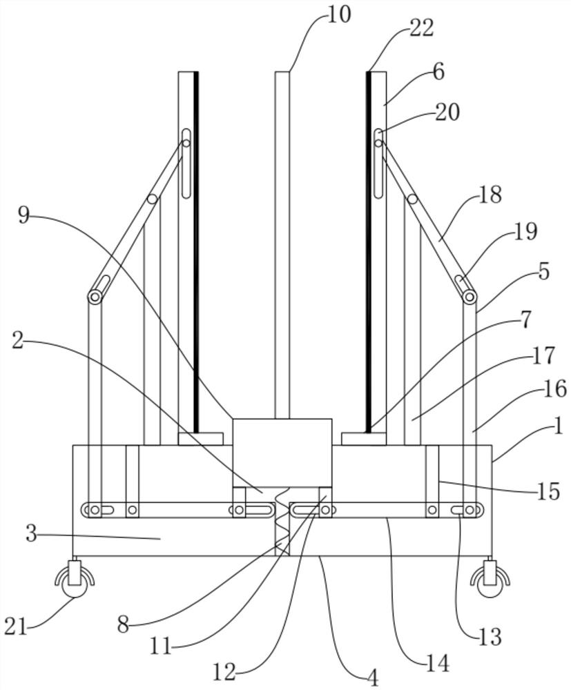
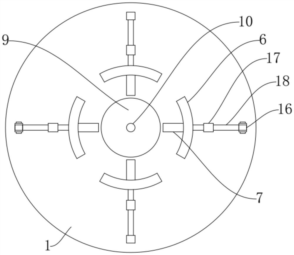
[0015] Such as Figure 1-2 As shown, the transformer winding drying constant voltage device of the present invention includes a base 1, a platform lifting hole 2, a transmission cavity 3, a first lever device 4, a second lever device 5, an extrusion plate 6, an extrusion chute 7, a reset Spring 8, winding platform 9 and winding shaft 10, the base 1 is arranged in a circular shape, the platform lifting hole 2 runs through the upper wall of the ba...
PUM
Abstract
The invention discloses a transformer winding drying constant pressure device, which includes a base, a platform lifting hole, a transmission cavity, a first lever device, a second lever device, an extrusion plate, an extrusion chute, a return spring, a winding platform and a winding shaft. The base is arranged in a circular shape, the platform lifting hole is set in the center of the base, the transmission cavity is set in the base, the return spring is vertically set in the center of the transmission cavity, and the winding platform is set in the platform lifting hole , the winding shaft is set on the winding platform, the extrusion chute is fixed on the upper wall of the base, the extrusion plate is slidably set on the extrusion chute, and the first lever device is set on the transmission space In the cavity, the second lever device is arranged above the base and outside the extrusion plate. The invention belongs to the technical field of transformer production, and specifically provides a transformer winding drying constant voltage device with tight clamping, continuous and constant clamping force, simple operation, high safety, high practicability, easy movement and low cost.
Description
technical field [0001] The invention belongs to the technical field of transformer production, in particular to a transformer winding drying constant voltage device. Background technique [0002] During the vacuum drying process of transformer windings, a constant pressing force must be applied to the windings to improve the mechanical strength of the windings and the stability of the box size, enhance the short-circuit resistance of the windings, and avoid the use of windings after vacuum drying. Coil press presses the winding process to improve production efficiency. [0003] The traditional winding device used in the vacuum drying process is a hydraulic device. Although the hydraulic device can exert a constant pressing force on the winding, the structure of the hydraulic device is complex, bulky, expensive, and requires maintenance. The production cost of the transformer winding is increased, and the clamping operation of the winding on the hydraulic equipment is very t...
Claims
Application Information
Patent Timeline
Application Date:The date an application was filed.
Publication Date:The date a patent or application was officially published.
First Publication Date:The earliest publication date of a patent with the same application number.
Issue Date:Publication date of the patent grant document.
PCT Entry Date:The Entry date of PCT National Phase.
Estimated Expiry Date:The statutory expiry date of a patent right according to the Patent Law, and it is the longest term of protection that the patent right can achieve without the termination of the patent right due to other reasons(Term extension factor has been taken into account ).
Invalid Date:Actual expiry date is based on effective date or publication date of legal transaction data of invalid patent.