
A Spectral Response Design Method Based on Neural Network

A technology of spectral response and neural network, applied in neural learning methods, biological neural network models, spectrometry/spectrophotometry/monochromator, etc. Integrating accuracy and other issues to achieve simple design process, improved optimization effect, and strong pertinence

Active Publication Date: 2021-08-17
ZHEJIANG UNIV +1
View PDF4 Cites 0 Cited by
  • Summary
  • Abstract
  • Description
  • Claims
  • Application Information

AI Technical Summary

Problems solved by technology

Although there have been recent attempts to use deep learning for reverse design, its stability needs to be improved
Reverse design network based on deep learning is difficult to achieve the fitting accuracy of forward prediction network

Method used


Image

  • A Spectral Response Design Method Based on Neural Network
  • A Spectral Response Design Method Based on Neural Network
  • A Spectral Response Design Method Based on Neural Network

Examples


Embodiment 1

[0053] A neural network-based spectral response design method implemented, the specific scheme is as follows:

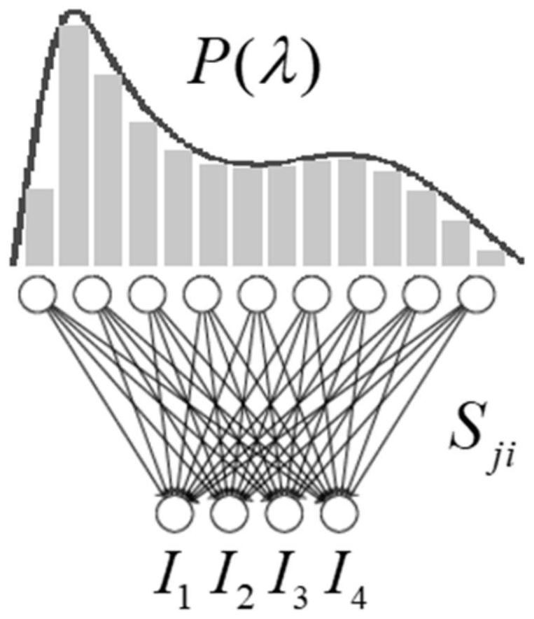
[0054] (1) Determine the target spectral range λ min =420nm, λ max =720nm and spectral resolution Δλ=1nm, then λ min , lambda max The number of spectral channels between N=(λ max -λ min ) / Δλ=300. It is determined that the spectral modulator is an optical film filter, the number of which is M=50.

[0055](2) Construct a neural network, which is called a spectral perception network. The first layer of the network is set as a linear connection layer with an input unit number of 300 and an output unit number of 50, and the linear connection layer is called a hardware layer. Then the weight term w ji Represents the spectral response value of the j-th filter at the i-th spectral channel.

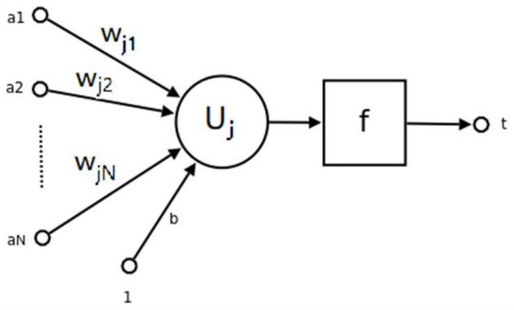
[0056] (3) Set the software layer network after the hardware layer. The specific setting method is to set a layer of batch normalization layer (BatchNormalization Layer), then s...

Embodiment 2

[0062] A neural network-based spectral response design method implemented, the specific scheme is as follows:

[0063] (1) Determine the target spectral range λ min =380nm, λ max =780nm and spectral resolution Δλ=2nm, then λ min , lambda max The number of spectral channels between N=(λ max -λ min ) / Δλ=200. It is determined that the spectral modulator is a photonic crystal device, the number of which is M=16.

[0064] (2) Construct an artificial neural network, and the first layer of the network is set as the number of input units is 200, the number of output units is a linear connection layer of 16, and the linear connection layer is called the hardware layer. Then the weight w between the i-th (i=1,2,…,200) input unit and the j-th (j=1,2,…,16) output unit of the hardware layer ji Represents the response value of the jth spectral modulator at the ith spectral channel.

[0065] (3) Set the software layer network after the hardware layer. The specific setting method is t...


PUM


Abstract

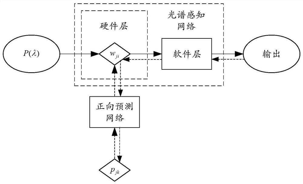
The invention discloses a neural network-based spectral response design method. The combination of spectral modulators with different spectral responses can be regarded as a linear connection layer of the neural network. At the same time, another neural network is used to add constraints to the generation of the parameters of this linear connection layer. Through the training of the entire neural network, not only can The optimization of the spectral response of the spectral modulator is achieved, and the corresponding design parameters can be directly generated, so as to be applied to scenarios such as spectral identification, spectral detection, and spectral imaging. Compared with the traditional optimization method, the optimization target of the present invention is clear, it is easier to evaluate the advantages and disadvantages of the optimization result, and the optimization effect is better; and the collaborative design of hardware and software is realized, and the design parameters can be flexibly adjusted to adapt to different applications Scenarios; at the same time, it avoids the design process that relies too much on experience, and provides a highly versatile design framework for the reverse design of spectral modulation devices.

Description

technical field [0001] The invention belongs to the fields of photoelectric detection, spectrum analysis, photoelectric devices and optical imaging. The invention can be applied to the spectral response design of various spectrometers, spectral imaging devices, and spectral detectors, so as to be applied to spectral analysis and high-resolution imaging, agricultural and agricultural product detection, and the fields of hygiene, medicine, and health. Background technique [0002] Spectral detection technologies such as spectrometers and spectral imaging provide great convenience for people to understand material properties and identify targets. Traditional spectral detection equipment is difficult to enter consumers' lives due to its complex structure, large size, bulky, expensive and other shortcomings. In recent years, with the introduction of software algorithms such as compressed sensing and machine learning into spectral detection, a large number of computational spectr...

Claims


Application Information

Patent Timeline
Patent Type & Authority Patents(China)
IPC IPC(8): G01J3/28G06N3/08G06N3/063
CPCG01J3/28G01J3/2823G06N3/063G06N3/08
Inventor 郝翔宋洪亚张文屹刘旭
Owner ZHEJIANG UNIV
Learn More